What Standards Govern Terminal Block Testing?
Terminal block testing in China is anchored in the GB/T 14048 low-voltage switchgear and controlgear family. The product standard for copper-conductor terminal blocks is GB/T 14048.7-2016 — Low-voltage switchgear and controlgear — Part 7-1: Ancillary equipment — Terminal blocks for copper conductors — which is modified-adopted from IEC 60947-7-1. The general provisions (clearance, creepage, insulation coordination, dielectric properties) are pulled from GB/T 14048.1, which mirrors IEC 60664-1. Together these two documents define the type tests, routine tests, and acceptance thresholds a terminal block must clear before it ships.
For projects that must also satisfy North American markets, UL 1059 (Standard for Terminal Blocks) applies in parallel — it reuses the same physical phenomena (temperature rise, voltage drop, dielectric withstand) but with different sample counts and limits. Testing to GB/T 14048.7 is the baseline for the domestic market; UL 1059 and IEC 60947-7-1 extend coverage for export. Knowing which framework applies up front prevents a test report from being rejected at the customer's incoming inspection.
How Is the Temperature Rise Test Performed?
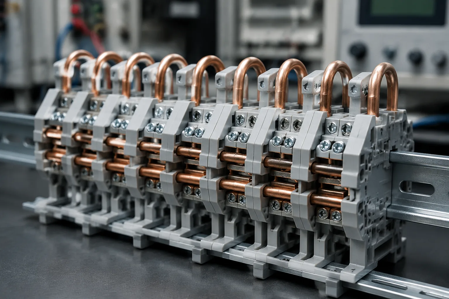
Temperature rise is the single most consequential type test for a terminal block, because the Joule heat generated at the contact interface is what ages insulation, loosens clamping, and ultimately causes field failures. The procedure under GB/T 14048.7 / IEC 60947-7-1 is prescriptive:
- Mount five terminal blocks side by side on a standard 35 mm DIN rail.
- Wire them in series using PVC-insulated conductors of the rated cross-section (e.g. 2.5 mm², 4 mm², 6 mm²), with 1 m conductor loops between blocks.
- Pass a test current equal to the current-carrying capacity of that cross-section until thermal equilibrium is reached.
- Record the temperature at the middle terminal block, taken as close as possible to the clamping point.
The pass criterion is unambiguous: at an ambient of roughly +20 °C, the temperature rise must not exceed 45 K (IEC 60947-7-1, clause 8.4.5). A voltage-drop measurement is taken before and after the heating cycle — if either reading drifts, the contact has degraded during the test, even if the temperature stayed within budget.
What Is the Voltage Drop Limit and Why Does It Matter?
Voltage drop is the proxy for contact resistance. Per IEC 60947-7-1, a direct test current equal to 0.1 × the rated current-carrying capacity of the cross-section is applied, and the drop is measured within 10 mm of the centre of each terminal point. At room temperature (~20 °C) the voltage drop must not exceed 3.2 mV per terminal block, and after any subsequent mechanical or thermal test it must not exceed 1.5 × the initial measured value.
These two numbers are the diagnostic core of a terminal block report. A reading of 3.2 mV is the ceiling; well-made blocks typically sit well below it. When we see a sample approach the limit, the root cause is almost always one of: oxidised contact surface, insufficient clamping force after screw tightening, or a conductor/barrel mismatch. The voltage-drop test catches defects that a continuity check alone cannot — continuity only confirms a path exists, not that the path is low-resistance.
How Are Clearance and Creepage Distances Verified?
Clearance (shortest path through air) and creepage distance (shortest path along the insulation surface) are verified by dimensional measurement against GB/T 14048.1 / IEC 60664-1 tables. The required minimums are a function of three inputs:
- Rated impulse withstand voltage — derived from the nominal system voltage and the overvoltage category (I–IV). Category III is the default for terminal blocks in fixed installations.
- Pollution degree — degree 3 (conductive pollution that becomes conductive through condensation) is the typical assumption for industrial terminal blocks.
- Insulating material group — groups I, II, IIIa, IIIb, classified by comparative tracking index (CTI).
For a 300 V system, overvoltage category III, pollution degree 3, the required impulse withstand voltage is 4000 V, demanding a minimum clearance of 3.0 mm. The same conditions set creepage distance by RMS working voltage and material group — for 500 V and material group I, creepage must reach 6.3 mm. These are not target values to design down to; they are floors. A dimensional check with calibrated gauges confirms the as-built product meets them, and a power-frequency dielectric test (below) functionally validates that the insulation path actually holds.
What Does the Dielectric Withstand Test Prove?
The dielectric (power-frequency withstand) test confirms the insulation system survives the voltage stress it is rated for. GB/T 14048.7 / IEC 60947-7-1 requires a test voltage held for 60 seconds between adjacent terminal blocks and between the blocks and the DIN rail. The applied voltage is selected from a table keyed to the rated insulation voltage (Ui):
| Rated insulation voltage Ui | Test voltage (r.m.s.) |
|---|---|
| Ui ≤ 60 V | 1000 V |
| 60 V < Ui ≤ 300 V | 1500 V |
| 300 V < Ui ≤ 690 V | 1890 V |
| 690 V < Ui ≤ 800 V | 2000 V |
The test passes if there is no flashover and no disruptive breakdown, and creepage current stays below 100 mA. This is distinct from the impulse withstand voltage test (1.2/50 µs waveform, 10 pulses of alternating polarity), which proves the clearance dimension rather than the bulk insulation. Both are required — dielectric for the solid insulation path, impulse for the air gap.
How Is Short-Time Withstand Current Tested?
Short-time withstand current proves the terminal block survives a fault long enough for the upstream protective device to trip. The test loads the block at a current density of 120 A/mm² of the rated cross-section for 1 second. For a 240 mm² high-current block, that is a 28,800 A pulse. Protective-conductor (PE) terminal blocks are subjected to three such runs; feed-through blocks to one.
After the pulse, the block must show no damage and remain serviceable, and the voltage-drop test must still pass — no flashover, no melting, no loosened clamp. This test is what separates a terminal block that merely carries rated current from one that survives the moment when something downstream shorts. It is the test most often omitted in cheap compliance reports, and the one most likely to correlate with field incidents.
What Mechanical Tests Are Required?
Mechanical integrity is verified through two test families under GB/T 14048.7. The pull-out (tension) test confirms the clamping unit holds the conductor: after tightening to the specified torque, a defined axial pull force is applied, and the conductor must not shift by more than the allowed amount nor pull free. The force scales with rated cross-section — a 2.5 mm² block is held to a lower pull value than a 16 mm² block, reflecting the conductor's own mechanical strength.
The mechanical strength of clamping units test subjects the screw or screwless clamping mechanism to repeated tightening and loosening cycles. For screw-type blocks, the clamping screw must be ISO metric thread and withstand the prescribed number of operating cycles without stripping or deforming. After the cycle test, a voltage-drop measurement confirms the contact has not degraded. For screwless (spring-cage, push-in) blocks, the relevant ageing test is the cycling stress that simulates years of thermal expansion and contraction — this is where long-term reliability is actually proven, not in a single pull test.
How Do You Verify a Terminal Block for Protective Conductor (PE) Applications?
PE terminal blocks fall under GB/T 14048.7 protective-conductor scope and IEC 60947-7-2, with a stricter voltage-drop allowance: the drop measured across the DIN rail must not exceed 6.4 mV (double the feed-through limit of 3.2 mV), reflecting the longer fault-current path through the rail itself. They also undergo three short-time withstand runs instead of one, because the PE conductor is the path that clears a fault — its terminal cannot be the weak link.
The consequence for procurement: a terminal block marked for PE use is not interchangeable with a generic feed-through block of the same footprint. A test report that lumps the two together, or that omits the PE-specific rail voltage-drop measurement, is incomplete for any installation where equipment earthing is a compliance requirement.
How Does the GB/T Framework Map to IEC and UL?
For laboratories and buyers working across regions, the standard correspondence is the practical reference:
| Scope | China (GB/T) | International (IEC) | North America (UL) |
|---|---|---|---|
| Terminal blocks, copper conductor | GB/T 14048.7-2016 | IEC 60947-7-1:2025 | UL 1059 |
| Protective conductor blocks | GB/T 14048.7 (PE scope) | IEC 60947-7-2 | UL 1059 |
| General provisions, insulation coordination | GB/T 14048.1 | IEC 60664-1, IEC 60947-1 | UL 1059 |
| Plug-in / pluggable connectors | — | IEC 61984 | UL 1977 |
GB/T 14048.7-2016 currently tracks IEC 60947-7-1:2009; IEC has since released the 2025 edition (which adds formal requirements for test-disconnect terminal blocks in its Annex D). For most type-test purposes the parameters — 45 K rise, 3.2 mV drop, 120 A/mm² short-time — are aligned across GB/T, IEC, and UL, with differences concentrated in sample counts, ambient assumptions (GB/T and IEC assume ~20 °C; UL 1059 uses 25 °C with a 30 K rise limit), and use-group distance tables.
Our Testing Capabilities
Beijing ZKGX Research provides terminal block testing against the GB/T 14048.7 and IEC 60947-7 frameworks for manufacturers, system integrators, and incoming-inspection teams.
Type and routine tests available:
- Temperature rise test (45 K limit, five-sample DIN-rail setup)
- Voltage drop / contact resistance (3.2 mV ceiling, pre/post-cycle)
- Power-frequency dielectric withstand (up to 2200 V per Ui table)
- Impulse withstand voltage (1.2/50 µs, 6–8 kV)
- Short-time withstand current (120 A/mm² × 1 s)
- Clearance and creepage dimensional verification (per GB/T 14048.1 / IEC 60664-1)
- Pull-out force and clamping-unit mechanical strength
- PE terminal block rail voltage-drop (6.4 mV) and triple short-time runs
Sample types we test: feed-through terminal blocks, PE/protective conductor blocks, fuse terminal blocks, pluggable and screwless (spring-cage, push-in) blocks, on DIN rail or standalone, from 0.2 mm² up to high-current 240 mm² cross-sections.
If you have a terminal block batch that needs a GB/T 14048.7 type-test report — for CCC conformity support, customer incoming inspection, or a design verification ahead of a UL 1059 submission — contact our laboratory with the rated cross-section, rated current, and applicable standard, and we will scope the test plan.
FAQ
What is the difference between a type test and a routine test for terminal blocks?
A type test is run once on a representative sample to validate a product design (e.g. the full temperature-rise and short-time withstand sequence). A routine test is performed on every production unit before shipment — typically just a dielectric withstand check at reduced voltage and a mechanical/visual inspection. GB/T 14048.7 defines both; a compliance report must distinguish them.
Can one test report cover both GB/T 14048.7 and UL 1059?
Partially. The physical tests overlap, but the sample counts, ambient conditions (20 °C vs 25 °C), and distance tables differ. A laboratory that understands both frameworks can run a combined programme, but the report must state each result against the specific standard — mixing them silently is the most common reason an incoming-inspection report gets rejected.
Why does my terminal block pass continuity but fail voltage drop?
Continuity only confirms an electrical path exists. Voltage drop measures the resistance of that path under load current. A contact that reads "beep" on a continuity tester can still have high resistance from oxidation, a marginal clamp, or a barrel/conductor mismatch — and will show up as an elevated millivolt reading under the 0.1× rated-current test. Voltage drop is the diagnostic that catches what continuity misses.
How often should terminal blocks be re-tested in service?
Type testing applies at design and major-change milestones. In service, periodic inspection focuses on torque retention (re-tightening to spec), thermography under load (hot spots indicate rising contact resistance), and voltage-drop trend monitoring. There is no fixed re-test interval in GB/T 14048.7 for field units — it is driven by the installation's maintenance standard and operating environment.
Does GB/T 14048.7 cover pluggable / push-in terminal blocks?
GB/T 14048.7 covers both screw-type and screwless (spring-cage, push-in) clamping units. For pluggable connector interfaces (the plug-to-socket half), the relevant additional reference is IEC 61984, which adds insertion-cycle durability and the derating curve as a function of pole count and ambient temperature. A complete report for a pluggable block often cites both.