Understanding the Drop Ball Impact Test
What the Test Evaluates
The drop ball impact test measures how well a material or coating withstands a sudden, concentrated impact from a falling ball. It reveals resistance to cracking, delamination, and substrate exposure. This method is commonly used for painted surfaces, plated finishes, plastic components, and laminated glass, providing a straightforward indicator of toughness and interlayer adhesion quality.
Key Inspection Items During the Test
Ball Specifications and Impact Energy
The mass and diameter of the ball are fundamental parameters that directly determine impact severity. A solid steel ball of a specified weight is used, with the drop height set to achieve the required impact energy. Inspectors verify the ball's condition, checking for surface defects or deformation, and confirm the calculated energy value matches the test specification.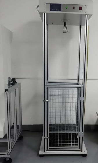
Drop Height and Guide Tube Alignment
The vertical drop height is precisely measured from the bottom of the ball to the specimen surface. A guide tube ensures the ball follows a straight path without rotation or lateral movement. Proper alignment is essential to ensure that the impact point is accurate and reproducible, preventing off-center strikes that can invalidate results.
Specimen Preparation and Conditioning
Test panels or parts must be clean, flat, and free of pre-existing defects. Conditioning at a standard temperature and humidity is often required befOre testing, as coating brittleness can vary with temperature. The inspection checklist includes verifying panel thickness, substrate material, and coating film thickness to ensure consistency across the test batch.
Impact Point Location and Number of Impacts
Multiple impacts at predefined locations are usually performed on a single specimen, with sufficient spacing to avoid interference between damaged zones. The number of tests per panel and their exact positions are documented, providing a statistically meaningful dataset for evaluating overall impact resistance.
Post-Impact Visual Examination
Immediately after impact, the test area is examined for cracks, circular delamination, and flaking. The size and shape of any damaged area are recorded. A magnifying lens or low-power microscope may be used to detect micro-cracks at the impact perimeter, which often indicate the onset of coating failure.
Adhesion and Coating Integrity Check
A tape adhesion test is frequently applied over the impacted zone. A pressure-sensitive tape is firmly pressed and then rapidly removed, and any lifted coating is assessed against standardized rating charts. This inspection item reveals weakened interlayer adhesion that may not be visible through simple visual inspection alone.
Quantitative Depth and Diameter Measurement
The indentation depth and diameter are measured using a depth gauge or optical profilometer. These values show the plastic deformation caused by the impact and are compared against acceptance limits. A deep, sharp indentation with radial cracks points to insufficient flexibility or adhesion in the coating system.
Common Failure Modes and Result Interpretation
Failure may occur as cohesive failure within a coating layer or as adhesive failure at the interface. The test report identifies the mode, along with all measured values and ratings. This information helps determine whether the material or coating meets durability requirements for its intended application without any external reference to specific regulatory documents.