Electronic Component Failure Analysis: Methods and Root Cause Investigation
Electronic component failure analysis determines root causes of performance degradation or catastrophic failures through systematic investigation combining non-destructive inspection, electrical characterization, and destructive physical analysis. The process identifies failure mechanisms at component, interconnect, and board levels, enabling corrective actions to improve reliability, optimize performance, and prevent recurrence in manufacturing, inspection, and field applications.
Why Failure Analysis Matters
Electronic systems continue shrinking in size while becoming more complex and pervasive. Failures cause costly downtime, product delays, recalls, and reputational damage. Understanding failure origins enables targeted risk mitigation and quality improvement across the component lifecycle.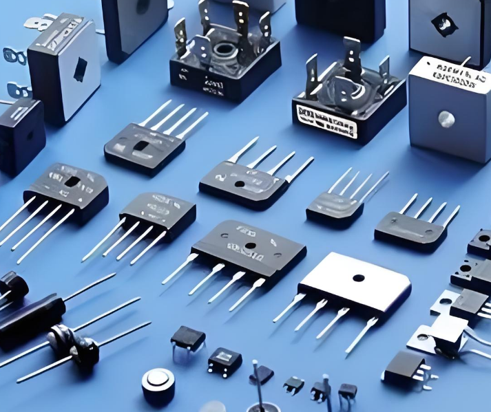
Benefits by stakeholder:
- Component manufacturers: Detect material, handling, process, and testing issues to improve quality and yield
- Component users: Understand failure origins and apply targeted prevention techniques
- Equipment designers: Identify improper component selection, inadequate derating, or external stress issues
Common corrective actions:
- Switching suppliers or component types
- Replacing defective lots
- Re-screening and testing to isolate weak units
- Process and design modifications
Failure Analysis Workflow
A systematic approach narrows potential causes from external appearance to internal construction:
- External visual inspection: Evaluate package and seal conditions
- Electrical test verification: Characterize behavior using curve tracers and parametric testing
- Material and metallurgical analysis: Employ SEM, FTIR spectroscopy, and EDS
- Mechanical and solderability testing: Identify structural issues and soldering defects
- Advanced inspections: Acoustic microscopy, real-time X-ray, leak tests, particle detection (P.I.N.D.)
- Decapsulation and internal analysis: Detailed optical inspections to locate internal defects
Failure Classification
Electronics typically fail in one of three locations:
- Within a component: Die damage, wire bond failure, delamination, capacitor cracking
- At interconnects: Solder joint failure, lead fracture, contact degradation
- Within the PCB: Trace fracture, via cracking, contamination-induced leakage, CAF formation
Failures follow the bathtub curve—most occur near beginning (infant mortality) and end (wearout) of component lifetime. Burn-in procedures detect early failures.
Component-Level Failures
Packaging Failures
Packaging-related failures constitute the majority of electronic part failures. The package barrier between components and environment is susceptible to:
- Thermal expansion mismatch: Mechanical stress causing material fatigue
- Humidity and chemical exposure: Corrosion of packaging materials and leads
- Temperature extremes: Wire bond overstress, die cracking, package cracking
- Encapsulation defects: Severed or shorted bonding wires, die cracks from thermal shock
- Ionic contamination: Migration of alkali metals and halogens causing corrosion or parameter deterioration
Wire Bond Failures
Wire bond breaking: Fracture under mechanical stress. Identified via X-ray microscopy and acoustic microscopy.
Wire bond liftoff: Ball bond breaks at intermetallic connection and lifts off bond pad. Causes include chemical contamination or incorrect bonding pressure. Cross sectioning confirms; SEM/EDS reveals contamination.
Delamination
Separation of molding compound from die or lead frame creates moisture ingress potential causing short circuits. Acoustic microscopy identifies delamination non-destructively; cross sectioning confirms.
Capacitor Cracking
Multi-layer chip capacitors (MLCCs) crack under mechanical flexure or thermal shock:
- Flex cracking: Excessive board bending during depaneling, connector insertion, or fixturing
- Thermal shock cracking: Sudden temperature increase from improper soldering
3D X-ray and acoustic microscopy identify cracking; cross sectioning confirms and reveals root cause through crack morphology.
Die Damage
Mechanical/thermo-mechanical overstress: Physical die cracking creating open circuits. Identified via acoustic microscopy and X-ray.
Electrical overstress (EOS) / ESD: Subtle damage requiring decapsulation. Surface damage visible with optical microscopy or SEM; deeper damage requires SQUID magnetic imaging or thermal imaging under electrical stress.
Semiconductor Failure Mechanisms
- Electromigration: Atomic movement from active regions causing dislocations and point defects
- Hot carrier injection: Charge accumulation in gate oxide affecting threshold voltage
- Latchup: Parasitic SCR structure causing overcurrent failure
- Gate sinking: Electromigration in MESFETs with aluminum gates
- Intermetallic formation: Degradation of ohmic contacts
Interconnect-Level Failures
Solder Fatigue
Temperature cycling over extended time causes solder joint cracking driven by CTE mismatch between PCB and component. Accelerated by potting stresses, vibration, and component size. Optical inspection, X-ray, and cross sectioning identify fatigue; dye-and-pry techniques locate cracking on BGAs.
Solder Overstress
Single mechanical event (drop, shock) fractures solder joint. Overstress fractures show larger gaps than fatigue cracks. Optical microscopy and cross sectioning identify.
Lead Fracture
Metal lead breaks between board and component body while solder joint remains intact. Common on large electrolytic capacitors and thin gull wing leads under vibration and shock.
Board-Level Failures
Contamination-Induced Current Leakage
Short circuits between traces or leads in humid environments when board cleanliness is inadequate. Ion contamination analysis determines if levels meet industry standards.
Conductive Anodic Filament (CAF) Failure
Metal migration along laminate fibers, typically between closely spaced plated through holes. Caused by drill damage or poor glass/resin bonding, exacerbated by humidity. Temperature/humidity bias testing assesses risk; cross sectioning confirms presence.
Plated Through Hole Fatigue
Thermal cycling causes:
- Barrel cracking: Plating fracture within the via
- Trace cracking: Connection break between PTH barrel and trace
X-ray microscopy identifies; cross sectioning confirms.
Pad Cratering and Trace Fracture
Pad cratering: Mechanical stress causes pad to rip off board, creating crater-shaped crack in laminate under BGA pads. Identified via 3D X-ray, dye-and-pry, or cross sectioning.
Trace fracture: Thin trace breaks at stress concentration points. Difficult to locate; requires knowledge of electrical networks and mechanical loads.
Failure Analysis Techniques
Non-Destructive Methods
| Technique | Application |
|---|---|
| Optical microscopy | Visual inspection, surface defects |
| X-ray microscopy (2D/3D) | Internal structure, wire bonds, solder joints |
| Acoustic microscopy | Delamination, voids, cracks |
| Curve tracing | Electrical characterization, pin-level isolation |
| Thermal imaging | Hot spots, thermal runaway |
| Time domain reflectometry | Impedance discontinuities, opens/shorts |
Destructive Methods
| Technique | Application |
|---|---|
| Decapsulation | Expose die for inspection |
| Cross sectioning | Internal structure, crack morphology |
| Dye and pry | Solder joint crack identification on BGAs |
| Wire bond pull/shear | Bond strength measurement |
| Focused ion beam (FIB) | Site-specific cross sections, circuit edit |
Material Analysis
- SEM/EDS: Morphology and elemental composition
- FTIR spectroscopy: Organic contamination identification
- Raman spectroscopy: Molecular structure analysis
- X-ray diffraction: Crystal structure, stress measurement
Electrical Overstress and ESD
ESD Failure Mechanisms
- Oxide breakdown: Field strengths above 6-10 MV/cm
- Junction damage: Reverse-bias leakage increasing to short
- Metallization burnout: Melting or vaporizing interconnects
- Charge injection: Hot carriers into oxide layer
ESD Failure Modes
- Catastrophic: Junction burnout, metallization burnout, oxide punch-through (require highest discharge voltages, easiest to test)
- Parametric: Parameter shifts causing stress test failure
- Latent: Delayed failures from weakened structures (most common, 4-10× parametric failures)
FIB Circuit Edit for Debug and Validation
Focused ion beam circuit edit enables rapid debugging and validation of design fixes without costly full mask spins, particularly valuable at advanced process nodes below 28nm.
Applications:
- Debug and optimize devices in production
- Explore and validate design changes
- Prototype new devices without mask fabrication
- Provide samples for test and qualification teams
- Accelerate time-to-market
Process: Gallium ion beam images, etches, and deposits materials with nanoscale precision. CAD navigation using GDS files locates areas of interest. Material removal and deposition create probe points and modify circuitry.
Laboratory Requirements
Equipment Capabilities
- High-resolution microscopy (optical, SEM, TEM)
- X-ray systems (2D and 3D)
- Acoustic microscopy
- Curve tracers and parametric test equipment
- Thermal imaging systems
- FIB for circuit edit and cross sectioning
- SQUID magnetic imaging for subtle EOS/ESD damage
- Laser timing probe for non-contact waveform acquisition
Expertise Requirements
- Component to system-level knowledge
- Electrical and physical analysis capabilities
- Materials science and failure mechanism understanding
- Parallel processing capability for large projects
- Scalability for client needs
Methodology and Best Practices
Systematic Approach
- Define electrical failure signature: Characterize the failure mode
- Isolate failure location: Component, interconnect, or board level
- Develop hypotheses: Based on failure mode and environmental conditions
- Apply appropriate techniques: Non-destructive before destructive
- Validate or reject hypotheses: Through incremental findings
- Identify failure mechanism: Root cause determination
- Recommend corrective actions: Prevention strategies
Customization Requirements
Each situation requires tailored approach based on:
- Component type and packaging
- Environmental conditions and stress history
- Failure mode and symptoms
- Board complexity and accessibility
- Available sample quantity
Preventing Failures Through Testing
- Electrical characterization: Parametric verification
- Functional testing: Operation validation
- Reliability qualification: Accelerated life testing
- environmental testing: Temperature cycling, humidity, vibration
- Screening: Burn-in, visual inspection, X-ray
Effective electronic component failure analysis requires comprehensive, multi-disciplinary methodology combining electrical and physical analysis. Partner with laboratories having specialized equipment, experienced personnel, and systematic workflows to identify root causes, determine failure mechanisms, and implement preventive measures for improved reliability and quality.