Table of Contents
- What is the ESD immunity test?
- The standard stack: IEC 61000-4-2, GB/T 17626.2, ISO 10605, MIL-STD-461
- The four test levels and the contact / air discharge split
- The 150 pF / 330 Ω RC network and the four ISO 10605 networks
- The current waveform parameters: rise time, peak, 30 ns, 60 ns
- Contact discharge vs air discharge: when to use each
- The test setup: GRP, HCP, VCP, and the 0.5 m insulation
- The test procedure: 10 discharges × 2 polarities × all test points
- The performance criteria A / B / C and the acceptance
- ESD simulator calibration: Annex B, the 4 GHz target, ISO 17025
- Component-level ESD: HBM, MM, CDM — distinct from system-level IEC 61000-4-2
- FAQ
- Our ESD immunity testing capabilities
What is the ESD immunity test?
The Electrostatic Discharge (ESD) immunity test is the laboratory simulation of the rapid transfer of electrostatic charge from a human body (or from a charged object a human is holding) to an electronic product, performed to verify that the product continues to operate correctly during and after the discharge. The test uses an ESD simulator (the "ESD gun") that stores a defined charge in a capacitor (150 pF for the commercial standard) and discharges it through a defined resistor (330 Ω) into the equipment under test (EUT). The simulator is applied to the user-accessible points of the EUT — connectors, keys, slots, seams, and the enclosure faces — and the EUT's functional response is observed and classified per the standard's performance criteria.
ESD is one of the most common electromagnetic disturbances in the field — generated by a person walking on a synthetic carpet, sliding a plastic enclosure across a desk, picking up a charged phone, or handling a cable connector. The discharge is a high-voltage (2-15 kV), high-peak-current (3.75 A per kV of contact voltage), very-fast-rise-time (0.7-1 ns) transient that couples into the EUT by conduction (through the touched connector) and by radiation (from the discharge arc to the nearby circuit board). An EUT with inadequate ESD immunity may suffer a reset, a program crash, a data corruption, or — at the high end — a permanent semiconductor failure.
The ESD immunity test is governed internationally by IEC 61000-4-2:2008 (Edition 2, the basic EMC publication per IEC Guide 107), in China by GB/T 17626.2-2018 (the identical adoption of IEC 61000-4-2:2008), in the automotive industry by ISO 10605:2008 + Amd 1:2022 (which adds the four RC networks specific to the road-vehicle environment), and in the military by MIL-STD-461G CS118 (the US Department of Defense personnel-borne ESD test). A product placed on the EU market must satisfy IEC 61000-4-2 under the EMC Directive 2014/30/EU; on the Chinese market, GB/T 17626.2; on the US commercial market, IEC 61000-4-2 via the FCC's typical reference; and for automotive applications, ISO 10605. The ESD test is one of the most frequently invoked EMC immunity tests, and a product that fails ESD cannot be placed on any major market.
The standard stack: IEC 61000-4-2, GB/T 17626.2, ISO 10605, MIL-STD-461
A complete ESD immunity testing project draws on a stack of international, Chinese, automotive, and military standards.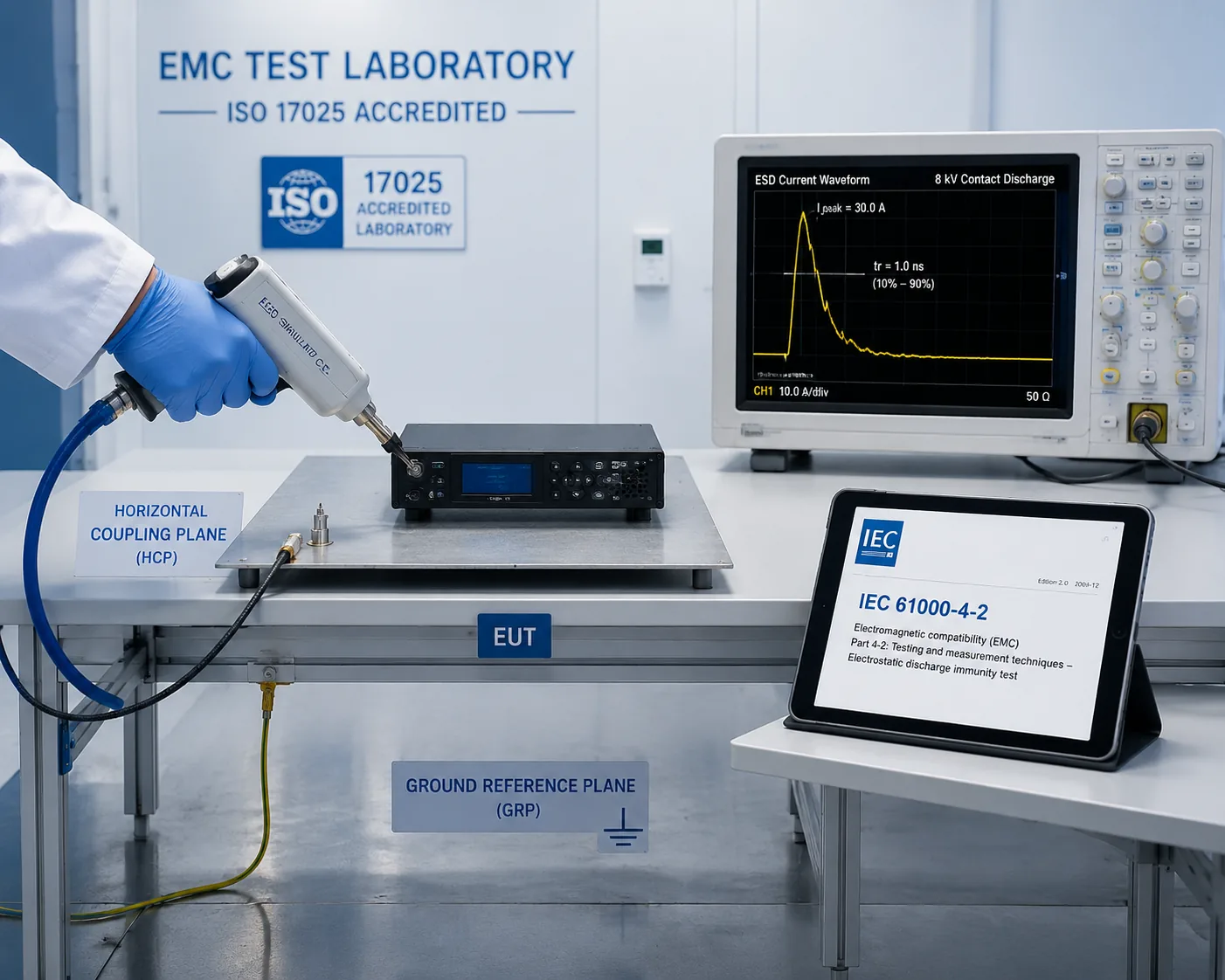
| Family | Standard | Scope |
|---|---|---|
| IEC 61000-4-2:2008 (Edition 2) | Electromagnetic compatibility (EMC) — Part 4-2: Testing and measurement techniques — Electrostatic discharge immunity test | The international basic EMC publication; the 150 pF / 330 Ω network; the four test levels (2/4/6/8 kV contact, 2/4/6/15 kV air); the test setup; the calibration of the simulator (Annex B); measurement uncertainty |
| GB/T 17626.2-2018 (≡ IEC 61000-4-2:2008, IDT) | 《电磁兼容 试验和测量技术 静电放电抗扰度试验》 | The Chinese national standard, identical adoption of IEC 61000-4-2:2008; the NMPA / SAMR-mandated reference for the ESD test on Chinese-market products |
| GB/T 18595-2024 | General EMC immunity standard for lighting equipment (one example of the Chinese product-family standards that call up GB/T 17626.2) | One of the many Chinese product-family standards that invoke GB/T 17626.2 with a specified test level and performance criterion |
| GB 4343.2-2020 (≡ CISPR 14-2) | EMC immunity requirements for household appliances and similar equipment | A product-family standard that calls up GB/T 17626.2 for household appliances |
| ISO 10605:2008 + Amd 1:2022 | Road vehicles — Test methods for electrical disturbances from electrostatic discharge | The automotive ESD standard; the four RC networks (150 pF/330 Ω, 330 pF/330 Ω, 150 pF/2000 Ω, 330 pF/2000 Ω) for the passenger-compartment and exterior-services situations; the ungrounded-EUT test protocol; test levels up to 25 kV |
| MIL-STD-461G CS118 | Personnel-borne ESD | The US military ESD test; 150 pF / 330 Ω network; test levels up to 15 kV; the calibration procedure in section 5.16.3.3 |
| MIL-STD-883 Method 3015 | ESD test for integrated circuits (HBM) | Component-level HBM ESD; distinct from the system-level MIL-STD-461 |
| JEDEC JS-001 | HBM ESD test for ICs | The component-level Human Body Model standard; 100 pF / 1500 Ω |
| JEDEC JS-002 | CDM ESD test for ICs | The component-level Charged Device Model standard |
| IEC 60749-26 | ESD test for semiconductors (MM) | The component-level Machine Model standard |
| ANSI/ESD S20.20 | ESD control program for electronics manufacturing | The manufacturing-environment ESD control (not a product test) |
| IEC 61340-3-1 | Simulation of ESD — HBM | The component-level HBM model (international equivalent of JEDEC JS-001) |
The single most consequential fact for a Chinese manufacturer is that GB/T 17626.2-2018 is the NMPA / SAMR-mandated standard for the ESD immunity test on the Chinese market. The Chinese product-family standards — GB 4343.2 for household appliances, GB/T 17799.2 for industrial equipment, GB/T 18595 for lighting, GB 4824 for industrial / scientific / medical equipment, the YY 9706.102 for medical devices — each call up GB/T 17626.2 with a specified test level and a specified performance criterion, and a product cannot be placed on the Chinese market unless it satisfies the applicable GB/T 17626.2 test.
The four test levels and the contact / air discharge split
IEC 61000-4-2:2008 defines four test levels, with different voltages for contact discharge and air discharge. The contact discharge levels are lower than the air discharge levels because the contact discharge is delivered directly to the conductive surface (a defined, repeatable current waveform), while the air discharge is delivered through a variable arc (with a less-defined waveform and a dependence on humidity, temperature, and approach speed).
| Level | Contact discharge voltage (kV) | Air discharge voltage (kV) |
|---|---|---|
| 1 | ± 2 | ± 2 |
| 2 | ± 4 | ± 4 |
| 3 | ± 6 | ± 6 |
| 4 | ± 8 | ± 15 |
The test levels are environmental — they correspond to the typical ESD events the product will encounter in its intended installation:
- Level 1 (2 kV): controlled-humidity environments (≥ 50 % RH), rarely-touched equipment
- Level 2 (4 kV): standard indoor environments, occasionally-touched equipment
- Level 3 (6 kV): standard indoor environments, frequently-touched equipment (keyboards, knobs, connectors)
- Level 4 (8 kV contact, 15 kV air): low-humidity environments (≤ 20 % RH), frequently-touched equipment, mobile / outdoor equipment
Most commercial product-family standards invoke Level 3 (6 kV contact, 6 kV air) for general indoor equipment and Level 4 (8 kV contact, 15 kV air) for portable / frequently-handled equipment. The IEC standard also allows test levels above Level 4 ("special") if the application requires — the automotive ISO 10605 standard, for example, goes up to 25 kV for the exterior-services module.
The 150 pF / 330 Ω RC network and the four ISO 10605 networks
The RC network of the ESD simulator — the discharge capacitor and the discharge resistor — defines the electrical characteristics of the discharge pulse and is the heart of the simulator design.
IEC 61000-4-2:2008 specifies a single RC network: 150 pF / 330 Ω. The 150 pF capacitor represents the typical capacitance of a human body to ground; the 330 Ω resistor represents the typical skin resistance of a human holding a metal object (a key, a tool). The 150 pF / 330 Ω network generates the canonical IEC 61000-4-2 current waveform (a 0.7-1 ns rise to a peak of 3.75 A per kV of charge voltage, followed by a slower decay to 50 % of peak at 30 ns and to near-zero at 60 ns).
ISO 10605:2008 specifies four RC networks for the automotive environment:
| RC network | Where used in the road vehicle | Why |
|---|---|---|
| 150 pF / 330 Ω (same as IEC 61000-4-2) | Passenger compartment, in the seat | Same body-capacitance / skin-resistance model as commercial |
| 330 pF / 330 Ω | Passenger compartment, outside the seat | The 330 pF represents a higher body-to-vehicle capacitance (the body is closer to the chassis when standing outside the seat) |
| 150 pF / 2000 Ω | Exterior services (under the hood, the boot, the charging port) | The 2000 Ω represents the higher resistance of an ESD through clothing or through a tool handle; the lower peak current but longer duration |
| 330 pF / 2000 Ω | Exterior services, larger body-to-vehicle capacitance | Combination of the two |
The automotive ESD test is therefore more complex than the commercial test: a given EUT may need to be tested with up to four different RC networks, each with its own test level, depending on the installation location in the vehicle. The simulator must be able to switch RC modules, which is why the commercial-grade Teseq NSG 435 or EM Test Dito ESD guns are not always sufficient for the automotive test, and the automotive-grade simulators (Teseq NSG 438, EM Test dito with the automotive kit) are used.
The current waveform parameters: rise time, peak, 30 ns, 60 ns
The IEC 61000-4-2:2008 current waveform is the defining characteristic of the ESD pulse — the parameter that the simulator must reproduce and that the calibration (Annex B) verifies. The waveform has four defining parameters:
| Parameter | Value at Level 4 (8 kV contact) | Definition |
|---|---|---|
| Rise time (t_r) | 0.7-1 ns | The time for the current to rise from 10 % to 90 % of the peak — the very fast initial edge that gives the ESD pulse its high-frequency content and its coupling efficiency into the EUT |
| Peak current (I_p) | 30 A (= 3.75 A/kV × 8 kV) | The maximum instantaneous current — proportional to the charge voltage; 3.75 A per kV of contact voltage is the IEC 61000-4-2 constant |
| Current at 30 ns (I_30) | 15 A (50 % of I_p) | The "knee" of the waveform — the transition from the fast initial peak to the slower decay |
| Current at 60 ns (I_60) | 4 A (~13 % of I_p) | The "tail" of the waveform — the energy dissipated in the EUT's protection circuits |
The waveform is measured on an ESD target (a 2 Ω Pardise-style coaxial current-measuring resistor, calibrated to 4 GHz per IEC 61000-4-2:2008 Edition 2) connected to a ≥ 1 GHz oscilloscope via a 20 dB attenuator and a low-loss coaxial cable. The calibration of the simulator, performed annually per ISO 17025, verifies that the waveform parameters are within the IEC 61000-4-2 tolerances at each of the four test voltages (2, 4, 6, 8 kV contact).
Contact discharge vs air discharge: when to use each
| Method | How applied | Repeatability | Use |
|---|---|---|---|
| Contact discharge | The simulator tip is held in direct contact with the conductive surface of the EUT (a connector shell, a metal enclosure, a screw head) and the discharge is initiated by a relay inside the simulator. | High — the waveform is defined by the simulator's RC network and is independent of humidity, temperature, and approach speed. | Preferred for any conductive accessible point; the reference method for IEC 61000-4-2 compliance |
| Air discharge | The simulator tip (rounded, 8 mm radius) is moved towards the EUT at the approach speed recommended by the standard until the arc strikes across the air gap. | Lower — the waveform depends on the arc length, which varies with humidity, temperature, approach speed, and the EUT surface geometry. | Used only where contact discharge is not possible (insulating surfaces, the user-accessible parts of a product that the user will touch but that are not conductive) |
Most IEC 61000-4-2 test plans specify contact discharge on all conductive accessible points and air discharge on insulating accessible points — the connector pins that are exposed when the connector is open, the buttons, the labels, the plastic seams. The contact discharge is applied to the conductive points of the connector shell; the air discharge is applied to the insulating surface around the connector. The contact discharge is the reference for the calibration and the primary compliance test; the air discharge is the practical-world simulation.
The test setup: GRP, HCP, VCP, and the 0.5 m insulation
The IEC 61000-4-2 test setup is designed to provide a reproducible electromagnetic environment and a reproducible coupling path for the ESD pulse. The setup for a tabletop EUT (the most common) consists of:
| Component | Specification | Function |
|---|---|---|
| Ground Reference Plane (GRP) | A copper or aluminium sheet ≥ 0.25 mm thick, ≥ 1 m × 1 m (typically 2 m × 2 m or larger), on the floor of the test room | The reference ground for the test; the return path for the ESD current |
| Horizontal Coupling Plane (HCP) | A copper or aluminium sheet 1.6 m × 0.8 m, on the wooden table | The capacitive coupling plane that simulates the table surface; the EUT sits on it, separated by a 0.5 mm insulating sheet |
| Vertical Coupling Plane (VCP) | A copper or aluminium sheet 0.5 m × 0.5 m, insulated from the HCP | The capacitive coupling plane that simulates a nearby vertical surface (a wall, a cabinet); used for the indirect discharge test |
| Wooden table | Non-conductive, 0.8 m high, supporting the HCP | The standard height for the EUT |
| Insulating support | 0.5 m thick insulator between the HCP and the EUT (typically a 0.5 mm polyethylene sheet) | The standardised capacitive coupling between the EUT and the HCP |
| Bleed resistors | Two 470 kΩ resistors, one between the HCP and the GRP, one between the VCP and the GRP | Discharge the coupling planes between pulses, preventing charge accumulation, while isolating them from the GRP during the pulse |
The EUT is placed on the insulating support on the HCP. The ESD simulator is applied (contact or air, direct or indirect to the HCP or the VCP) and the EUT's functional response is observed. The 0.8 m table height, the 1.6 m × 0.8 m HCP, the 0.5 m × 0.5 m VCP, and the 0.5 mm insulation are all specified by the standard to give a reproducible capacitive coupling path. A floor-standing EUT is placed on the GRP with a 0.1 m insulating support.
The test procedure: 10 discharges × 2 polarities × all test points
The IEC 61000-4-2 test procedure:
- Select test points — the user-accessible points where an ESD is plausible in normal use: connectors (pin and shell), buttons, keys, slots, seams, labels, the four faces of the enclosure. The standard excludes points that are only accessible during service.
- Apply contact discharge to the conductive points — at the highest specified test voltage (typically ± 4 / 6 / 8 kV), positive and negative polarity, 10 discharges per polarity per point (40 discharges per point total at 2 polarities × 2 methods), with an interval of ≥ 1 s between discharges.
- Apply air discharge to the insulating points — at the highest specified test voltage (typically ± 8 / 15 kV), positive and negative polarity, 10 discharges per polarity per point.
- Apply indirect discharge — to the HCP (the horizontal coupling plane) at 4 points around the EUT (the 4 sides), ± 4 / 6 / 8 kV, positive and negative, 10 discharges per polarity per point; and to the VCP (the vertical coupling plane) at the 4 sides of the EUT, ± 4 / 6 / 8 kV, positive and negative, 10 discharges per polarity per point.
- Observe the EUT during and after the discharge — classify the response per the performance criteria (see next section).
- For the automotive EUT — discharge the EUT between pulses (the EUT is ungrounded in the vehicle; the charge accumulates), using a 1 MΩ bleed resistor with a 220 pF capacitor to the GRP, per ISO 10605.
The test plan documents the test points, the test levels, the discharge method (contact / air / indirect), the polarity, the number of discharges, the performance criterion, and the result for each test point. A typical IEC 61000-4-2 test plan for a tabletop electronic product runs to 20-50 test points and 500-2000 individual discharges.
The performance criteria A / B / C and the acceptance
The IEC 61000-4-2 performance criteria, defined in IEC 61000-1-2 (or in the product-family standard that invokes the test), classify the EUT's response to the ESD pulse:
| Criterion | Definition | Typical result |
|---|---|---|
| A (Normal performance) | The EUT continues to operate as intended during and after the ESD; no degradation of any function below the normal performance specification. | The display does not flicker; the data link does not drop; the measurement is not corrupted. Pass. |
| B (Temporary degradation, self-recovery) | The EUT experiences a temporary loss of function or degradation of performance during the ESD, but recovers normal performance on its own after the ESD (without operator intervention). | A brief display glitch; a brief data-link error that the protocol recovers by re-transmission; a sensor reading that glitches but recovers. Pass for most product-family standards. |
| C (Temporary degradation, operator intervention required) | The EUT experiences a loss of function or degradation of performance during the ESD that does not self-recover; the operator must reset, power-cycle, or otherwise intervene to restore normal operation. | A system hang that requires a power cycle; a data corruption that requires a re-load; a sensor that requires re-calibration. Fail for most product-family standards (some accept C for non-critical functions). |
| (Loss of function, permanent damage — implicit "Fail") | The EUT is permanently damaged by the ESD; a semiconductor fails; a flash memory is corrupted; a hardware component is destroyed. | Fail for every product-family standard. |
The acceptance criterion is set by the product-family standard, not by IEC 61000-4-2 itself. For most industrial, IT, and consumer products, the acceptance is Class A or B at the specified test level — the product must continue to operate normally (A) or self-recover (B) at the specified test voltage. Class C is acceptable for some non-critical functions in some product-family standards; permanent damage is never acceptable.
ESD simulator calibration: Annex B, the 4 GHz target, ISO 17025
The IEC 61000-4-2:2008 Annex B defines the calibration of the ESD simulator — the verification that the simulator produces the correct current waveform at each of the four test voltages. The calibration is performed annually (or more frequently if the product-family standard requires) at an ISO 17025-accredited calibration laboratory.
The calibration setup:
| Component | Specification | Function |
|---|---|---|
| ESD target | A 2 Ω Pardise-style coaxial current-measuring resistor, calibrated to 4 GHz per IEC 61000-4-2:2008 Edition 2 (the Edition 1 was 1 GHz; the Edition 2 extended the bandwidth to capture the full fast edge of the ESD pulse) | Converts the ESD current to a voltage for the oscilloscope |
| 20 dB attenuator | A 50 Ω coaxial attenuator | Protects the oscilloscope from the high peak voltage |
| Oscilloscope | ≥ 1 GHz analog bandwidth, ≥ 4 GS/s sampling rate | Captures the current waveform |
| Faraday cage | A shielded enclosure around the calibration setup | Prevents the radiated field of the ESD from corrupting the measurement |
| Coaxial cable | Low-loss, ≤ 1 m, calibrated | Connects the target / attenuator to the oscilloscope |
The calibration verifies that the four waveform parameters (rise time, peak current, current at 30 ns, current at 60 ns) are within the IEC 61000-4-2 tolerances at each of the four test voltages (2, 4, 6, 8 kV contact). The calibration certificate is the document that supports the traceability of the ESD test to the IEC standard.
Component-level ESD: HBM, MM, CDM — distinct from system-level IEC 61000-4-2
A common confusion is between the system-level ESD test (IEC 61000-4-2:2008, the 150 pF / 330 Ω ESD gun on the finished product) and the component-level ESD tests (the Human Body Model, the Machine Model, the Charged Device Model, applied to the bare integrated circuit). The two are distinct in their purpose, their levels, and their standards.
| Test | Level | RC network | Voltage | Standard | Purpose |
|---|---|---|---|---|---|
| IEC 61000-4-2 (system-level) | Finished product | 150 pF / 330 Ω | 2-8 kV contact, 2-15 kV air | IEC 61000-4-2 / GB/T 17626.2 | Verify the system survives the field ESD event |
| HBM (Human Body Model) | Bare IC | 100 pF / 1500 Ω | 500 V to 8 kV (Class 0 to Class 3B) | JEDEC JS-001 / IEC 61340-3-1 | Verify the IC survives the ESD from a charged person during handling (manufacturing, assembly) |
| MM (Machine Model) | Bare IC | 200 pF / 0 Ω (approx) | 100 V to 1 kV (Class M1 to M5) | JEDEC JESD22-A115 / IEC 60749-26 | Verify the IC survives the ESD from a charged machine (handler, tester) |
| CDM (Charged Device Model) | Bare IC (the IC is the source of the charge, not the target) | 4-30 pF / ~ 1 Ω (depends on package) | 125 V to 2 kV (Class C1 to C7) | JEDEC JS-002 / JESD22-C101 | Verify the IC survives the ESD when the IC itself is charged and discharges to a grounded conductor |
The component-level HBM, MM, and CDM tests are typically required by the integrated-circuit manufacturer and reported on the IC data sheet; the system-level IEC 61000-4-2 test is required by the product manufacturer and reported on the product's declaration of conformity. A system-level ESD failure (the product fails IEC 61000-4-2 at 6 kV) is fixed by adding system-level protection (TVS diodes, filtering, shielding) — not by changing the IC.
FAQ
What is the difference between contact discharge and air discharge in IEC 61000-4-2?
Contact discharge is applied directly to a conductive surface of the EUT (the simulator tip touches the surface); it gives a defined, repeatable current waveform and is the preferred compliance method. Air discharge is applied through an arc to an insulating surface (the rounded simulator tip approaches the surface until the arc strikes); it gives a less-repeatable waveform that depends on humidity, temperature, and approach speed, and is used only where contact discharge is not possible.
What are the four test levels of IEC 61000-4-2?
Level 1 (± 2 kV contact, ± 2 kV air), Level 2 (± 4 kV, ± 4 kV), Level 3 (± 6 kV, ± 6 kV), Level 4 (± 8 kV contact, ± 15 kV air). Most product-family standards invoke Level 3 for indoor equipment and Level 4 for portable / frequently-handled equipment. The automotive ISO 10605 extends to 25 kV for exterior services.
What is the GB/T 17626.2 standard?
GB/T 17626.2-2018 is the Chinese national standard, an identical adoption (IDT) of IEC 61000-4-2:2008. It is the NMPA / SAMR-mandated reference for the ESD immunity test on products placed on the Chinese market, invoked by the Chinese product-family standards (GB 4343.2 household appliances, GB/T 17799.2 industrial equipment, GB/T 18595 lighting, YY 9706.102 medical devices).
What is the difference between IEC 61000-4-2 and ISO 10605?
IEC 61000-4-2 is the commercial basic EMC standard (one RC network: 150 pF / 330 Ω; test levels up to 8 kV contact / 15 kV air). ISO 10605 is the automotive standard (four RC networks: 150 pF / 330 Ω, 330 pF / 330 Ω, 150 pF / 2000 Ω, 330 pF / 2000 Ω; test levels up to 25 kV; the ungrounded-EUT test protocol for the vehicle installation). A given automotive EUT may need to be tested with up to four different RC networks.
What is the difference between system-level ESD (IEC 61000-4-2) and component-level ESD (HBM)?
System-level IEC 61000-4-2 (150 pF / 330 Ω, 2-15 kV) tests the finished product's ability to survive the field ESD event. Component-level HBM (100 pF / 1500 Ω, 500 V to 8 kV) tests the bare IC's ability to survive the ESD from a charged person during manufacturing handling. A system-level failure is fixed by system-level protection; a component-level failure is fixed by IC-design protection.
Our ESD immunity testing capabilities
Beijing ZKGX Research (ISO/IEC 17025 accredited, CMA- and CNAS-accredited testing laboratory) provides complete ESD immunity testing across the IEC, GB, ISO, and MIL-STD standard stack:
- IEC 61000-4-2:2008 ESD immunity test — four test levels (2/4/6/8 kV contact, 2/4/6/15 kV air), contact and air discharge, direct and indirect to the HCP and VCP, 10 discharges × 2 polarities per test point, with the full IEC 61000-4-2 tabletop or floor-standing setup.
- GB/T 17626.2-2018 ESD immunity test — the Chinese national standard, identical adoption of IEC 61000-4-2:2008; for the NMPA / SAMR-mandated test on Chinese-market products, invoked by the product-family standards GB 4343.2 (household), GB/T 17799.2 (industrial), GB/T 18595 (lighting), YY 9706.102 (medical).
- ISO 10605:2008 + Amd 1:2022 automotive ESD — the four RC networks (150 pF/330 Ω, 330 pF/330 Ω, 150 pF/2000 Ω, 330 pF/2000 Ω), the passenger-compartment and exterior-services protocols, the ungrounded-EUT test, test levels up to 25 kV.
- MIL-STD-461G CS118 military ESD — 150 pF / 330 Ω network, test levels up to 15 kV, the section 5.16.3.3 calibration procedure.
- ESD simulator calibration — per IEC 61000-4-2:2008 Annex B, with the 4 GHz ESD target, the ≥ 1 GHz oscilloscope, the 20 dB attenuator, in a shielded Faraday cage; ISO 17025 calibration certificate.
- Performance-criterion evaluation — A / B / C classification per IEC 61000-1-2 and the product-family standard; functional monitoring of the EUT during the ESD test.
- Test-plan development — full IEC 61000-4-2 test-plan development (test points, test levels, discharge methods, polarities, criteria, results documentation) for the customer's product.
- Pre-compliance testing — in-house pre-compliance ESD test with a step-up voltage protocol to identify the failure threshold; supports the customer's design-fix cycle before the full-compliance test.
Suitable product categories include: IT and consumer electronics (smartphones, laptops, tablets, monitors, peripherals); household appliances (washing machines, refrigerators, microwave ovens); industrial equipment (PLCs, drives, instrumentation); lighting (LED drivers, luminaires); medical devices (IEC 60601 / GB 9706 family); automotive electronics (ECUs, infotainment, sensors, chargers — ISO 10605); military equipment (MIL-STD-461 CS118). Each project is delivered with a full data report (test plan, simulator calibration certificate, raw discharge data, performance-criterion classification, conclusion per the applicable standard) in English and/or Chinese, with CMA/CNAS stamping. Contact Beijing ZKGX Research to scope the ESD immunity test applicable to your product and target market.