What Standard Governs Proximity Switch Testing in China?
Proximity switch testing in China is governed by GB/T 14048.10-2016 Low-voltage Switchgear and Controlgear — Part 5-2: Control Circuit Devices and Switching Elements — Proximity Switches, which is technically equivalent to IEC 60947-5-2. The standard covers inductive, capacitive, ultrasonic, and photoelectric proximity switches that detect the presence of metallic and/or non-metallic objects without contact. A revision adopting IEC 60947-5-2:2019 is in the national-standard pipeline (CQC published the old/new edition differences in April 2026), with changes to the sensing-range and operating-distance clauses.
GB/T 14048.10 sits under the GB/T 14048 low-voltage switchgear family — the same family that governs terminal blocks (GB/T 14048.7), contactors, and circuit breakers. It is the mandatory CCC certification basis for proximity switches sold in the Chinese market: a proximity switch cannot be sold domestically without a CCC certificate citing GB/T 14048.10 compliance. For international trade, the IEC 60947-5-2 test report is cross-accepted via the IECEE CB Scheme.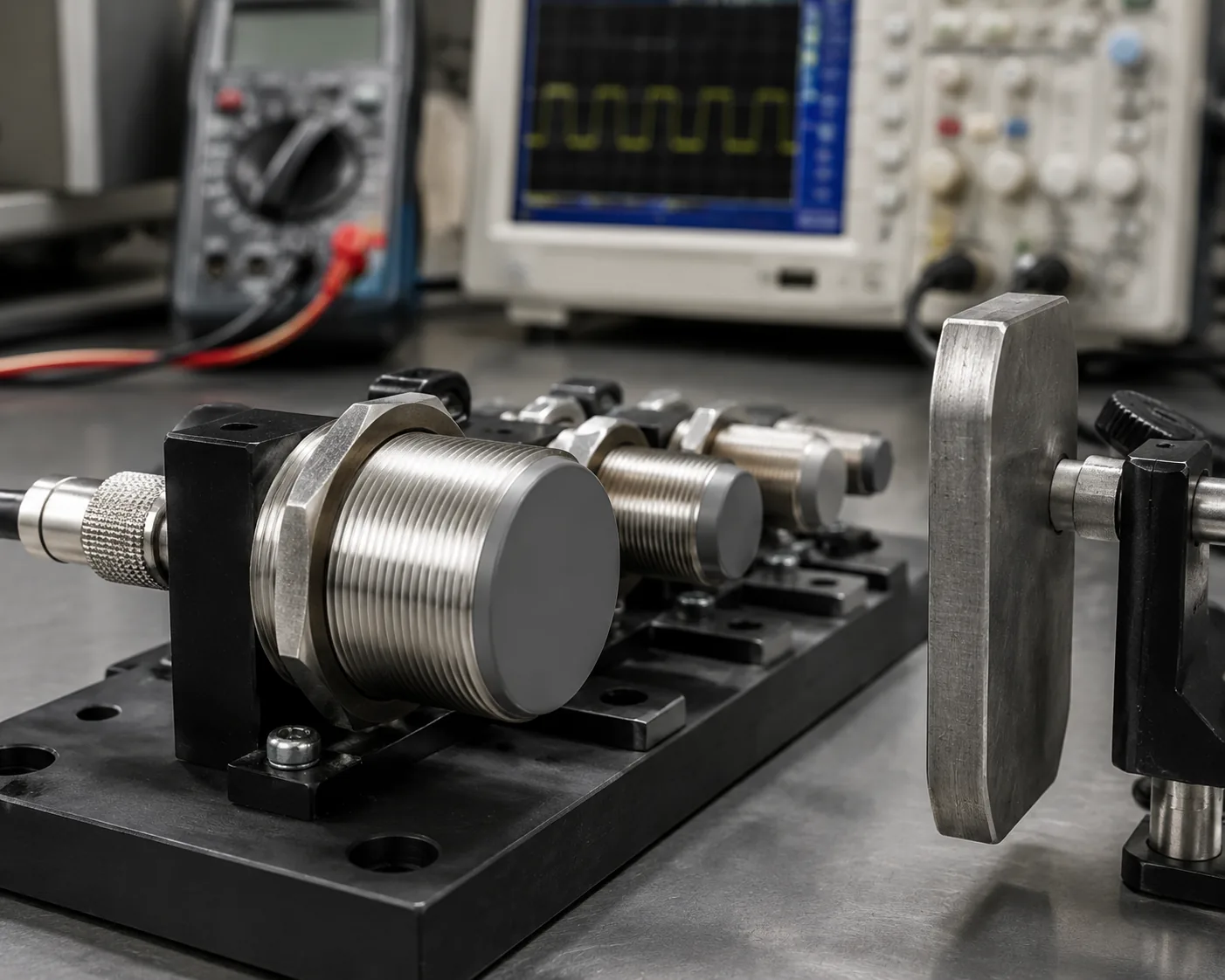
The standard defines the product by sensing technology (inductive / capacitive / ultrasonic / photoelectric), by mounting type (flush / embeddable vs non-flush / non-embeddable), by output logic (PNP / NPN × NO / NC), and by rated sensing distance. Knowing the type up front decides the entire test panel — an inductive flush-mounted switch is tested with a standard mild-steel target at a defined approach geometry, while a photoelectric retro-reflective switch is tested with a defined reflector at a defined beam-break geometry.
What Is the Sensing Distance Framework (Sn / Sr / Su / Sa)?
The sensing-distance framework is the core of GB/T 14048.10 and the part most often misapplied in the field. A proximity switch's detection distance is not a single number — it is a four-level hierarchy that distinguishes the rated, actual, usable, and assured distances.
| Symbol | Term | Meaning | Range |
|---|---|---|---|
| Sn | Rated sensing distance (额定动作距离) | The nominal value declared by the manufacturer on the data sheet and nameplate | A fixed declared value |
| Sr | Effective sensing distance (实际动作距离) | The measured distance on an individual switch at reference conditions (20 °C, rated voltage) | 0.9 Sn ≤ Sr ≤ 1.1 Sn |
| Su | Usable sensing distance (可用动作距离) | The measured distance over the allowed temperature and voltage range (−25 to +70 °C, 85–110 % voltage) | 0.81 Sn ≤ Su ≤ 1.21 Sn |
| Sa | Assured sensing distance (保证动作距离) | The distance within which the switch is guaranteed to trigger under any allowed condition | 0 ≤ Sa ≤ 0.81 Sn |
The practical implication: the reliable operating distance is 0.81 × Sn, not Sn. A switch rated at Sn = 10 mm is only guaranteed to detect a target within 8.1 mm — if the application places the target at 9.5 mm, the switch may detect it at room temperature and rated voltage but miss it at −25 °C or at 85 % supply voltage. The field-failure literature is full of cases where a switch "worked fine in the lab and missed in service" — the root cause is that the installation gap was set to Sn rather than to Sa.
The four-level hierarchy is why a GB/T 14048.10 type-test report does not give a single pass/fail distance. It reports the measured Sr at reference conditions, then verifies that Su stays within 0.81–1.21 Sn across the temperature and voltage envelope, and confirms that Sa (the guaranteed floor) is no greater than 0.81 Sn. A report that gives only "sensing distance = 10 mm, pass" is not a GB/T 14048.10 report — it is a marketing data sheet, not a test result.
How Is Repeat Accuracy Tested?
Repeat accuracy (重复精度, R) measures how consistently the switch triggers at the same distance over repeated approaches — the property that decides whether the switch produces a stable, jitter-free output or a noisy one that the controller must debounce. GB/T 14048.10 defines it as the spread of the measured operating distances over a defined number of approaches under the same conditions.
Test method: the standard target (a square mild-steel plate, 1 mm thick, with side length equal to the sensor's nominal face diameter, or as specified for non-inductive technologies) is approached axially toward the sensing face from outside the sensing range (from ≥ 120 % of Sn), at a slow controlled speed (typically ~0.1 mm/s for inductive switches). The approach is repeated at least 10 times under the same conditions. The repeat accuracy R is calculated from the maximum spread of the measured trigger points, expressed as a percentage of Sn.
Acceptance threshold: typical industrial-grade proximity switches carry R ≤ 3 % Sn; tighter grades reach ≤ 2 %. A switch with poor repeat accuracy will trigger at, say, 9.7 mm on one approach and 10.2 mm on the next — the controller sees this as timing jitter, and in counting applications (gear-tooth counting, bottle-line counting) it produces miscounts.
The repeat-accuracy test is the one that catches marginal electronics and marginal target geometry. A switch with a clean oscillator and a clean target approaches consistently; a switch with a drifting oscillator, a contaminated sensing face, or a target that is too small produces scatter. The test is run with the standard target precisely because a non-standard target (different material, smaller area, irregular shape) introduces its own variability that masks the switch's inherent repeat accuracy.
What Is Differential Travel (Hysteresis) and Why Is It Specified?
Differential travel (回差, H) is the distance between the switch's operate point (as the target approaches) and its release point (as the target recedes). When a target approaches an inductive switch at 10 mm the output turns ON; when it recedes, the output turns OFF at — typically — 9 mm, not at 10 mm. The 1 mm difference is the differential travel.
Why it is specified: without differential travel, a target sitting exactly at the trigger threshold would cause the output to oscillate ON-OFF-ON-OFF with the smallest mechanical vibration or electrical noise. The differential travel creates a dead band — a range of target positions where the output state does not change — that makes the output stable against small perturbations. This is the same function as hysteresis in a thermostat.
Acceptance threshold: GB/T 14048.10 / IEC 60947-5-2 requires the differential travel to be no greater than 20 % of Sr (effectively ≤ 10 % Sn for most practical switches). A switch with excessive hysteresis will fail to detect a target that reciprocates within the dead band — a reciprocating cam that moves 3 mm within a 4 mm hysteresis band will never trigger the release, and the controller will read a stuck-ON output.
The differential-travel test catches switches whose trigger/release thresholds have drifted apart — a sign of oscillator detuning or output-stage degradation. It is measured in the same axial-approach fixture as the repeat-accuracy test, recording the approach trigger point and the recession release point and taking the difference.
How Is Switching Frequency Tested?
Switching frequency (开关频率, f) is the maximum rate at which the switch can toggle its output ON and OFF while still producing clean, countable transitions. It is the parameter that decides whether a proximity switch can keep up with a high-speed counting application — a gear-tooth sensor on a 3000 rpm shaft with 60 teeth must switch at 3000 Hz, far above a standard 100 Hz proximity switch's rating.
Test method (inductive): a rotating disc of standard mild steel with defined teeth (typically a gear or a slotted disc with the standard-target geometry) is spun at increasing speed, with the sensor mounted at the standard sensing distance. The output is monitored on an oscilloscope, and the switching frequency is the maximum rotational speed at which the output transitions remain clean — full amplitude, no missed edges, no bounce. The standard test uses a defined load resistor (e.g. 3.9 kΩ or 7.8 kΩ between output and common, depending on PNP or NPN).
The result is reported in Hz and is technology-dependent: inductive switches typically run 100–3000 Hz depending on oscillator design; photoelectric switches can run higher; capacitive and ultrasonic switches are typically slower. A switch rated at 100 Hz cannot be used in a 500 Hz counting application regardless of its sensing distance or repeat accuracy — the frequency is the gating parameter.
The frequency test is where the oscilloscope is essential, not the multimeter. The multimeter's frequency mode averages over time and can report a plausible frequency for a switch that is actually dropping edges; only the oscilloscope shows whether every tooth produced a full, clean transition. This is the lesson from the field-failure literature — a marginal switch can pass a multimeter frequency check and fail an oscilloscope check.
What Are the Flush vs Non-flush Mounting Differences?
The mounting type — flush (埋入式, shielded, embeddable) vs non-flush (非埋入式, unshielded, non-embeddable) — changes the sensing-field geometry and therefore the test setup and the rated distance.
Flush (shielded): the sensing field is constrained by a metal ring around the sensing face, so the field exits predominantly axially. The switch can be mounted flush in a metal bracket without the bracket itself triggering the switch. The trade-off is a shorter rated sensing distance — typically Sn ≈ 0.5–1 × sensor diameter for inductive flush switches — because the shielding constrains the field.
Non-flush (unshielded): the sensing field extends radially as well as axially, so the switch must be mounted with a defined metal-free zone around the sensing face (typically a clearance of ≥ 3 × sensor diameter). The benefit is a longer rated sensing distance — typically Sn ≈ 1–2 × sensor diameter — because the unshielded field reaches further.
The test implication: the standard target for a flush switch is a mild-steel plate with side length equal to the sensor diameter; for a non-flush switch the standard target is typically larger (side length equal to 3 × sensor diameter), because the unshielded field interacts with a larger target area. A test that uses the wrong target for the mounting type gives the wrong Sn — and this is a common error in incoming-inspection testing, where one target size is used for all switches regardless of type.
How Are Output Logic and Electrical Safety Tested?
The output-logic and electrical-safety block verifies that the switch produces the correct electrical output and survives the electrical environment of industrial service.
Output logic (PNP / NPN × NO / NC): the switch is wired per its declared logic, powered at rated voltage, and the output is measured both at rest and at trigger. A PNP-NO switch sources positive voltage on the output when triggered (output rises toward +V); an NPN-NO switch sinks current (output falls toward 0 V). A PNP-NC inverts this; an NPN-NC inverts that. The test verifies the output toggles between the correct logic levels with the correct polarity. A mismatched PNP/NPN or NO/NC — a common installation error documented across the field-failure literature — produces a switch that "never detects" or "always detects" because the controller input is wired for the opposite logic.
Reverse polarity, overvoltage, and short-circuit protection: the switch is subjected to reverse supply polarity, a defined overvoltage, and an output short-circuit, and must survive without permanent damage. These are the tests that catch inadequate output-stage protection — the failure mode that kills proximity switches on factory floors when a wiring fault back-feeds the wrong voltage.
Dielectric and insulation: per the GB/T 14048.1 general provisions, the insulation between live parts and accessible metal (or the mounting bracket) is tested at a defined high voltage (typically 1 kV for SELV switches, up to 2.5 kV or 4 kV for mains-referenced switches), and no breakdown may occur. This is the same dielectric-strength framework as for terminal blocks and other switchgear.
How Are IP Rating and EMC Tested?
IP rating (ingress protection): proximity switches installed in industrial environments are routinely exposed to coolant, oil, washdown, and dust. The IP rating per GB/T 4208 (= IEC 60529) is verified by the standard dust-chamber and water-jet/immersion tests. Industrial proximity switches typically carry IP65, IP67, or IP68; an IP67 switch must survive 30 minutes at 1 m immersion, an IP68 switch must survive the manufacturer-declared immersion condition. A failed IP test means coolant or washdown water enters the housing and corrodes the electronics — the dominant field-failure mode for switches on machining centres and food-processing lines.
EMC (electromagnetic compatibility): the switch must not emit excessive conducted/radiated noise (emissions) and must tolerate a defined level of incoming noise (immunity). The EMC framework under GB/T 14048.1 and the IEC 61000-4 series includes:
- Radiated and conducted emissions (so the switch's oscillator does not interfere with other equipment)
- Immunity to radiated RF fields (IEC 61000-4-3, the test that catches switches that false-trigger near walkie-talkies or VFDs)
- Immunity to fast transients / burst (IEC 61000-4-4, on the supply and signal lines)
- Immunity to surge (IEC 61000-4-5)
- Immunity to conducted RF (IEC 61000-4-6)
The EMC immunity tests are where proximity switches most often fail in service without anyone realising the root cause. A switch that false-triggers intermittently near a variable-frequency drive, or that drops out when a nearby contactor opens, is usually passing its electrical and distance tests but failing EMC immunity — and only the EMC test panel catches this.
How Do Vibration and Shock Tests Apply?
Proximity switches on industrial machinery — CNC axes, conveyor lines, robots — see significant mechanical vibration and shock. GB/T 14048.10 invokes vibration and shock tests per the IEC 60068 series:
Vibration: the switch is subjected to sinusoidal vibration across a defined frequency range and amplitude (typically 10–500 Hz or 10–2000 Hz, at defined g level), in three axes. During and after the test, the sensing distance, repeat accuracy, and output logic must remain within spec. This catches switches whose internal oscillator detunes or whose potting cracks under vibration — the failure mode that produces the "intermittent when the spindle runs at high speed" symptom.
Shock: defined mechanical shocks (e.g. 30 g or 50 g, half-sine, defined duration) are applied in defined axes. The switch must survive without mechanical damage or performance drift. This catches switches whose ferrite cores or coil bobbins are inadequately potted — the failure mode from tool changes, part ejections, and accidental impacts.
A switch that passes the distance and electrical tests but fails vibration will work on the bench and fail on the machine — which is why the vibration and shock tests are part of the type-test panel, not an optional add-on.
Our Testing Capabilities
Beijing ZKGX Research provides proximity switch testing against GB/T 14048.10-2016 (IEC 60947-5-2), including the CCC certification test panel.
Sensing performance (the core type tests):
- Rated sensing distance Sn, effective Sr, usable Su, assured Sa — full four-level framework
- Repeat accuracy R (10+ approaches, ≤ 3 % Sn)
- Differential travel / hysteresis H (≤ 20 % Sr)
- Switching frequency f (rotating-target method, oscilloscope verification)
Electrical:
- Output logic verification (PNP/NPN × NO/NC)
- Reverse polarity, overvoltage, short-circuit protection
- Dielectric / insulation strength (per GB/T 14048.1)
- Supply voltage range (85–110 % rated, −25 to +70 °C)
Mechanical and environmental:
- Vibration (IEC 60068-2-6) and shock (IEC 60068-2-27)
- IP rating (GB/T 4208 / IEC 60529, IP20–IP68)
- EMC emissions and immunity (GB/T 14048.1, IEC 61000-4 series)
Technology scope: inductive, capacitive, ultrasonic, photoelectric proximity switches; flush and non-flush mounting types; PNP/NPN, NO/NC outputs; DC 3-wire and AC 2-wire variants.
If you need a GB/T 14048.10 type-test report for CCC certification, a sensing-distance verification for an incoming-inspection batch, a switching-frequency qualification for a high-speed counting application, an IP67 washdown qualification, or an EMC immunity test for a switch that false-triggers near VFDs — contact our laboratory with the switch technology, mounting type, output logic, rated Sn, and target standard, and we will scope the test plan.
FAQ
What is the difference between Sn, Sr, Su, and Sa in a proximity switch report?
Sn is the rated (nominal) sensing distance declared by the manufacturer. Sr is the effective distance measured on the individual switch at reference conditions (must be 0.9–1.1 × Sn). Su is the usable distance over the allowed temperature and voltage range (0.81–1.21 × Sn). Sa is the assured distance — the guaranteed-trigger floor under any allowed condition (≤ 0.81 × Sn). The reliable installation distance is Sa, not Sn — a target placed at 0.95 × Sn may be detected at room temperature and missed at −25 °C.
Why does my proximity switch work on the bench but miss detections on the machine?
The most common cause is an installation gap set to Sn rather than Sa — at room temperature and rated voltage the switch detects at ~Sn, but at temperature extremes or voltage dips the detection range contracts to Su's lower bound (0.81 × Sn), and a target at 0.95 × Sn is missed. The second common cause is a non-standard target (different material, smaller area, faster speed) that reduces the effective sensing distance. The third is EMC interference from nearby drives or contactors. A GB/T 14048.10 test report separates these by testing sensing at reference and extreme conditions, with the standard target, with EMC immunity.
What is the difference between flush and non-flush proximity switches, and why does it matter for testing?
Flush (shielded) switches have a metal ring that constrains the sensing field axially, allowing flush mounting in metal but giving a shorter rated distance. Non-flush (unshielded) switches have a radial+axial field, requiring a metal-free mounting zone but giving a longer rated distance. The test uses different standard targets — flush uses a target the size of the sensor face; non-flush uses a larger target (typically 3× sensor diameter). Using the wrong target for the mounting type gives the wrong Sn.
Why is switching frequency tested with an oscilloscope, not a multimeter?
Because the multimeter's frequency mode averages over time and can report a plausible frequency for a switch that is actually dropping edges or producing marginal-amplitude transitions. The oscilloscope shows the waveform — whether every tooth of the rotating target produced a full, clean transition with adequate amplitude and no bounce. A marginal switch can pass a multimeter frequency check and fail an oscilloscope check, producing miscounts in a high-speed application.
Is GB/T 14048.10 testing mandatory for selling proximity switches in China?
Yes — proximity switches are within the scope of the China Compulsory Certification (CCC) system, and GB/T 14048.10 is the certification basis. A proximity switch cannot be sold in the domestic market without a valid CCC certificate citing GB/T 14048.10 compliance. For international trade, the IEC 60947-5-2 test report is cross-accepted via the IECEE CB Scheme, and a CB Test Certificate reduces (but does not eliminate) re-testing for destination-country certifications.