Table of Contents
- What is radiated emission testing?
- The standard stack: CISPR 11/22/32, GB 4824/9254, FCC Part 15, EN 55032
- The test setup: semi-anechoic chamber, turntable, antenna mast
- Frequency bands, Class A vs Class B, and the limit lines
- Antennas: loop, biconical, log-periodic, horn
- The measurement receiver: peak, quasi-peak, average detectors
- Test procedure: height scan, turntable rotation, maximisation
- Cable and configuration control
- Pre-compliance vs full compliance testing
- FAQ
- Our radiated emission testing capabilities
What is radiated emission testing?
Radiated emission testing (also called radiated disturbances testing, or radiated EMI testing) is the measurement of the electromagnetic field strength unintentionally generated by an electronic product and radiated through space — the radio-frequency "noise" emitted by the product's digital circuits, switching power supplies, clocks, processors, display drivers, and motor controllers. The test measures the field strength at a defined distance (3 m, 10 m, or 30 m) from the product, in a calibrated semi-anechoic chamber (SAC) or an open-area test site (OATS), using a calibrated measurement receiver (spectrum analyser or EMI receiver) and a set of calibrated antennas (loop, biconical, log-periodic, horn). The result is compared against the applicable regulatory limit line, and the product passes if its maximum emission (after the height scan, the turntable rotation, and the maximisation) is below the limit at every frequency in the regulated band.
Every electronic product that contains a digital circuit — a microprocessor, a clock, a switching power supply, a wireless transmitter, or a motor driver — generates electromagnetic radiation as an unintended by-product. The switching voltages and currents in the digital circuit create time-varying electromagnetic fields that propagate through the air as radio-frequency waves. At low levels, these emissions are harmless; at high levels, they interfere with radio communications, television, GPS, aviation, and other electronic equipment. The radiated emission limit lines are set by the national and international standards bodies to ensure that the unintentional emissions from the product do not exceed the threshold at which interference with licensed radio services becomes likely.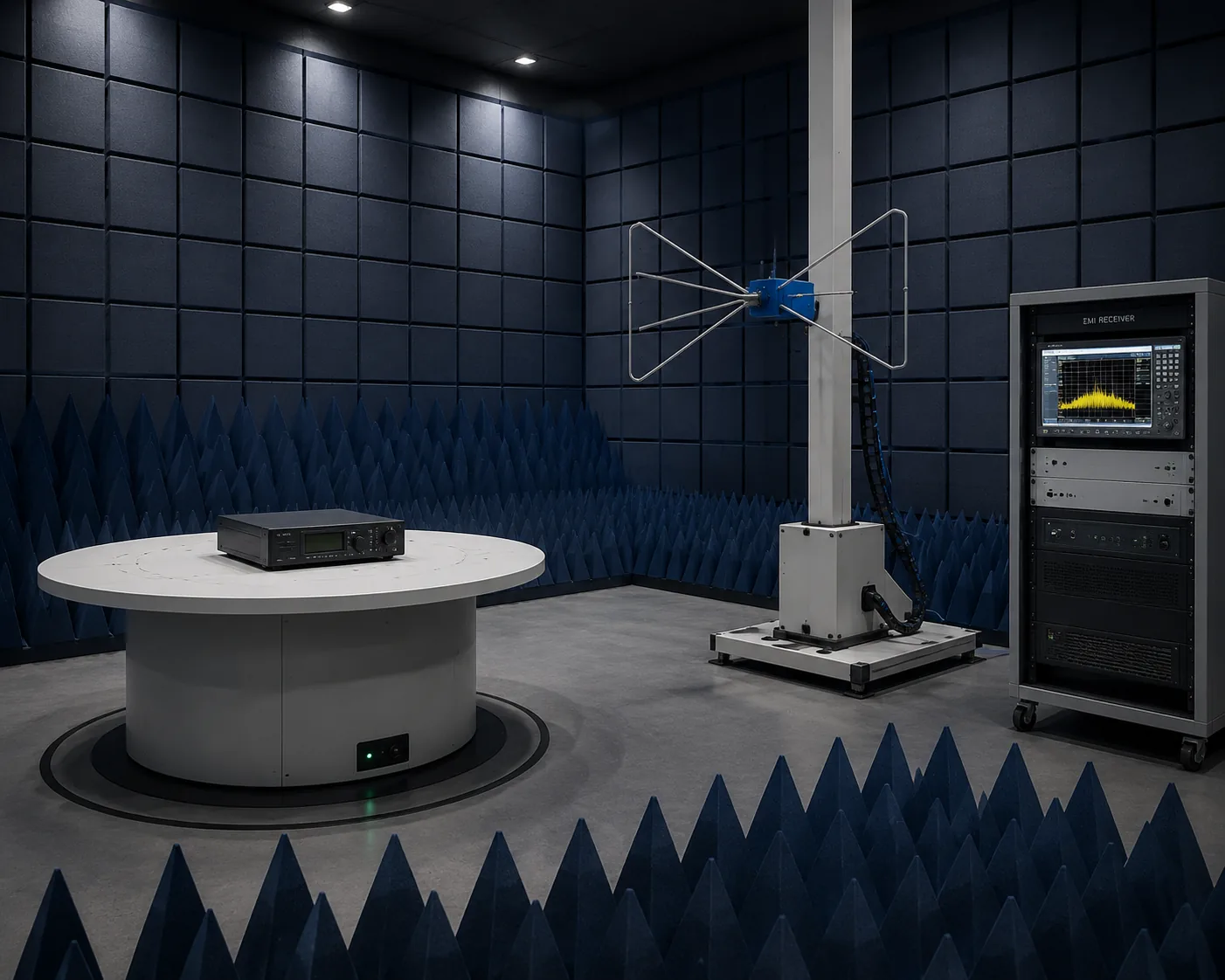
The standards governing radiated emission testing span the CISPR standards (the international Comité International Spécial des Perturbations Radioélectriques, now a part of the IEC) — CISPR 11 (industrial / scientific / medical), CISPR 32 (multimedia equipment, replacing the older CISPR 22 for IT equipment), CISPR 15 (lighting), CISPR 14-1 (household appliances); the FCC Part 15 (the US regulation for unintentional radiators); the EN 55032 / EN 55011 / EN 55015 / EN 55014-1 (the European adoptions of the CISPR standards); and the Chinese GB 9254 (≡ CISPR 32, multimedia), GB 4824 (≡ CISPR 11, industrial / scientific / medical), GB 17743 (≡ CISPR 15, lighting), and GB 4343.1 (≡ CISPR 14-1, household appliances). A product placed on the Chinese market must satisfy the applicable GB standard; on the EU market, the applicable EN standard under the EMC Directive 2014/30/EU; on the US market, the FCC Part 15 limits.
The standard stack: CISPR 11/22/32, GB 4824/9254, FCC Part 15, EN 55032
A complete radiated emission testing project draws on a stack of international, US, EU, and Chinese standards.
| Family | Standard | Scope |
|---|---|---|
| CISPR 32:2015 / A1:2019 / A2:2024 | Electromagnetic Compatibility of Multimedia Equipment — Emission Requirements | The international standard for multimedia equipment (IT, audio/video, broadcast receivers, information technology); replaces the older CISPR 22 and CISPR 13 |
| CISPR 11:2024 (Edition 6.1) | Industrial, Scientific and Medical Equipment — RF Disturbance Characteristics — Limits and Methods of Measurement | The international standard for ISM equipment (industrial equipment, medical equipment, scientific equipment) |
| CISPR 15:2018 / A1:2020 | Limits and Methods of Measurement of Radio Disturbance Characteristics of Electrical Lighting and Similar Equipment | The international standard for lighting equipment |
| CISPR 14-1:2020 | Requirements for Household Appliances, Electric Tools and Similar Apparatus — Emission | The international standard for household appliances |
| FCC 47 CFR Part 15 | Radio Frequency Devices — Unintentional Radiators | The US regulation; the Class A / Class B limits; the Declaration of Conformity / Verification / Certification routes |
| EN 55032:2015 + A1:2019 + A11:2021 | Electromagnetic Compatibility of Multimedia Equipment — Emission Requirements | The European adoption of CISPR 32 |
| EN 55011:2016 + A1:2019 | ISM Equipment | The European adoption of CISPR 11 |
| GB 9254-2008 (≡ CISPR 22:2006) / GB/T 9254-2024 (≡ CISPR 32:2015) | 《信息技术设备的无线电骚扰限值和测量方法》 / 《多媒体设备的无线电骚扰限值》 | The Chinese standard for IT / multimedia equipment |
| GB 4824-2019 (≡ CISPR 11:2016) | 《工业、科学和医疗设备 射频骚扰特性 限值和测量方法》 | The Chinese standard for ISM equipment |
| GB 17743-2021 (≡ CISPR 15:2018) | 《电气照明和类似设备的无线电骚扰特性的限值和测量方法》 | The Chinese standard for lighting equipment |
| GB 4343.1-2018 (≡ CISPR 14-1:2020) | 《家用电器、电动工具和类似器具的电磁兼容要求 第 1 部分:发射》 | The Chinese standard for household appliances |
| CISPR 16-1-1 / 16-1-4 / 16-2-3 | Specification for Radio Disturbance and Immunity Measuring Apparatus and Methods | The international standards for the measurement instrumentation (receiver, antennas, test site) |
| GB/T 6113.101 / .104 / .203 | 《无线电骚扰和抗扰度测量设备和测量方法规范》 | The Chinese adoption of CISPR 16 |
| ANSI C63.4-2014 | Methods of Measurement of Radio-Noise Emissions from Low-Voltage Electrical and Electronic Equipment in the Range of 9 kHz to 40 GHz | The US measurement-method standard invoked by FCC Part 15 |
The single most consequential fact for a Chinese manufacturer is that the applicable GB standard must be used for the Chinese market. The GB standards are now closely aligned with the CISPR standards (the 2024 revision of GB/T 9254 adopts CISPR 32:2015), making a single test report potentially acceptable across multiple markets — provided the test site, the instrumentation, and the reporting meet the requirements of each jurisdiction.
The test setup: semi-anechoic chamber, turntable, antenna mast
The radiated emission test is performed in a semi-anechoic chamber (SAC) — a shielded room with radio-frequency-absorbing material (ferrite tiles + pyramidal foam absorbers) on the walls and the ceiling, and a conductive ground plane (aluminum or steel sheet) on the floor. The absorbing material prevents reflections from the walls and ceiling (simulating free-space propagation); the ground plane provides the controlled reflection that is part of the measurement (the direct ray + the ground-reflected ray combine at the receiving antenna, and the height scan finds the maximum constructive-interference position).
| Component | Specification |
|---|---|
| Chamber size | 3 m chamber (3 m EUT-to-antenna distance) or 10 m chamber (10 m distance); the 10 m chamber is the reference distance for most CISPR limits, the 3 m chamber uses the inverse-distance extrapolation (20 log(10/3) = 10.5 dB correction) |
| Turntable | A motorised rotating table on which the EUT is placed; 360° rotation; the test scans all azimuthal angles to find the maximum emission direction |
| Antenna mast | A motorised vertical mast that raises and lowers the receiving antenna between 1 m and 4 m; the test scans all heights to find the maximum (the ground-reflected ray creates a height-dependent interference pattern) |
| Ground plane | A flat conductive surface (aluminum, steel, or copper mesh) covering the entire chamber floor; the flatness must be within a few mm to maintain the controlled reflection |
| Absorbing material | Ferrite tiles (for the 30-1000 MHz range) + pyramidal foam absorbers (for the 1-40 GHz range); the combined absorber stack provides ≥ 20 dB absorption across the frequency range; the chamber's normalised site attenuation (NSA) must be within ± 4 dB of the theoretical (CISPR 16-4-2) |
The open-area test site (OATS) is the historical reference — an outdoor test site with a ground plane and no walls (no absorbing material needed because there are no walls to reflect). The OATS is still used as the calibration reference, but the SAC is the practical test facility for most modern laboratories (the SAC provides the shielded environment, the temperature control, and the year-round availability that the OATS cannot).
Frequency bands, Class A vs Class B, and the limit lines
The radiated emission limits are defined by two parameters: the frequency range and the equipment class (Class A for industrial/commercial or Class B for residential/consumer).
Frequency ranges (CISPR 32 / GB 9254):
- 30 MHz – 230 MHz — the lower VHF/UHF band; the limits are tighter (lower) than the higher frequencies
- 230 MHz – 1000 MHz — the UHF band; the limits step up by 4-6 dB at 230 MHz
- 1 GHz – 3 GHz — the microwave band; for products with internal clocks > 108 MHz, the test extends to 1-6 GHz (or higher, per CISPR 32 Table A.1)
- 3 GHz – 6 GHz — for products with internal clocks > 500 MHz
- 6 GHz – 18 GHz — for products with very high internal frequencies (5G, Wi-Fi 6E)
Class A vs Class B (CISPR 32 / GB 9254):
| Parameter | Class A (commercial / industrial) | Class B (residential / consumer) |
|---|---|---|
| Definition | Equipment marketed for use in a commercial / industrial environment | Equipment marketed for use in a residential environment |
| Limit stringency | Less stringent (higher limit, by ~10 dB) | More stringent (lower limit, by ~10 dB) |
| 3 m chamber limit (30-230 MHz QP) | 50 dBµV/m | 40 dBµV/m |
| 3 m chamber limit (230-1000 MHz QP) | 57 dBµV/m | 47 dBµV/m |
| 10 m chamber limit (30-230 MHz QP) | 40 dBµV/m | 30 dBµV/m |
| 10 m chamber limit (230-1000 MHz QP) | 47 dBµV/m | 37 dBµV/m |
| FCC Part 15 (3 m, 30-88 MHz QP) | 49.6 dBµV/m | 40.0 dBµV/m |
The Class B limits are ~10 dB tighter than the Class A limits, reflecting the assumption that residential equipment is closer to the receiving antenna (the TV, the radio) and must be quieter. Most consumer products (smartphones, laptops, home appliances) are Class B; most industrial equipment (PLCs, motor drives, medical imaging) are Class A.
Antennas: loop, biconical, log-periodic, horn
The radiated emission test uses four antenna types, each covering a specific frequency range:
| Antenna | Frequency range | Polarisation | Use |
|---|---|---|---|
| Loop antenna | 9 kHz – 30 MHz | Magnetic field (H-field) | For the low-frequency emissions from switching power supplies and motor controllers; the loop is placed 50 cm from the EUT (not on the antenna mast) |
| Biconical antenna | 30 MHz – 300 MHz | Linear (horizontal and vertical, switched by rotating the antenna 90°) | For the VHF emissions; the bowtie shape provides a broad bandwidth |
| Log-periodic antenna | 200 MHz – 1 GHz | Linear (horizontal and vertical) | For the UHF emissions; the multi-element array provides directionality and broadband response |
| Broadband / hybrid (biconilog) | 30 MHz – 1 GHz (or 2 GHz) | Linear | A combined biconical + log-periodic antenna that covers the entire 30 MHz – 1 GHz range in one sweep; the most commonly used antenna for modern CISPR 32 testing |
| Horn antenna | 1 GHz – 18 GHz (or 40 GHz) | Linear | For the microwave emissions; the waveguide horn provides the directivity and the gain needed at the GHz frequencies |
Each antenna must be calibrated by an accredited antenna-calibration laboratory per CISPR 16-1-4 / CISPR 16-1-5, with the antenna factor (AF) in dB/m tabulated at each frequency. The measured voltage at the receiver output is converted to the field strength by: E (dBµV/m) = V (dBµV) + AF (dB/m) + cable loss (dB).
The measurement receiver: peak, quasi-peak, average detectors
The EMI measurement receiver (or the spectrum analyser in EMI mode) uses three detector types, each with a specific purpose:
| Detector | Purpose | Response time |
|---|---|---|
| Peak detector | The fastest scan; captures the maximum amplitude at each frequency; used for the pre-scan to identify the emission frequencies quickly | Fast (microseconds per point) |
| Quasi-Peak (QP) detector | The regulatory detector for CISPR / FCC compliance; weights the emission by its repetition rate (a continuous emission reads higher than an intermittent emission at the same peak amplitude); the QP has a defined charge time (1 ms for 9-150 kHz band; 1 ms for 150 kHz-30 MHz; 1 ms for 30 MHz-1 GHz) and a discharge time (160 ms) | Slow (up to 1.5 s per point for the full QP settle) |
| Average detector | The regulatory detector for the average limits (CISPR 32 has both QP and average limits above 1 GHz); captures the average of the emission over time | Medium |
The test strategy is: scan with the peak detector to identify the emission frequencies (fast); then re-measure the identified frequencies with the quasi-peak detector to obtain the regulatory value (slow but compliant). A peak reading that is already below the QP limit guarantees a QP pass (the peak is always ≥ the QP), so only the frequencies where the peak is above the QP limit need the slow QP measurement.
Test procedure: height scan, turntable rotation, maximisation
The CISPR 32 / GB 9254 test procedure for the 30 MHz – 1 GHz band:
- Place the EUT on the turntable at 0.8 m height (tabletop) or on the floor (floor-standing), 1 m from the rear edge of the turntable.
- Configure the EUT in the worst-case operating mode (maximum emission) — all ports active, all wireless transmitters in the standby mode (not transmitting), all displays on, all motors running.
- Select the antenna — biconilog for 30 MHz – 1 GHz; horn for 1-6 GHz.
- For each antenna polarisation (horizontal, then vertical):
- Scan the frequency range with the peak detector to identify the emission frequencies
- For each identified frequency, perform the height scan (raise the antenna from 1 m to 4 m in 0.5-1 m steps) and the turntable rotation (rotate 360° in 5-15° steps) simultaneously, finding the maximum emission
- At the maximum-emission height and angle, measure with the quasi-peak detector
- Repeat for the other antenna polarisation.
- Record the six worst-case emissions (typically) — the frequency, the polarisation, the turntable angle, the antenna height, the measured QP value, and the margin to the limit.
- Compare against the applicable Class A or Class B limit; the product passes if all QP values are below the limit.
For the 1-6 GHz band, the procedure is similar but uses the near-field probe scan for frequencies close to the EUT (the EUT is scanned at 3 m distance with a horn antenna; for EUTs > the wavelength at the test frequency, a near-field probe scan at 10-20 cm distance identifies the emission hotspots).
Cable and configuration control
The cable layout is one of the most critical (and most frequently mis-specified) aspects of the radiated emission test. The cables connected to the EUT (power, signal, USB, Ethernet, display) act as unintentional antennas — the RF currents from the EUT flow on the cable shields and radiate. The CISPR 32 standard specifies the cable layout (the "excess cable" is bundled and hung at a defined height; the cables to the auxiliary equipment are routed at a defined geometry). A cable that is mis-routed can add 10-20 dB to the measured emission — the difference between pass and fail.
The EUT configuration must represent the worst-case emission — all ports connected, all peripherals active, the maximum processing load, the wireless transmitter in the mode that generates the most spurious emission. The configuration must be documented in the test report.
Pre-compliance vs full compliance testing
| Aspect | Pre-compliance | Full compliance |
|---|---|---|
| Test site | Open lab bench, or a small shielded room; no calibrated chamber | Calibrated 3 m or 10 m SAC or OATS with NSA within ± 4 dB |
| Instrumentation | Any spectrum analyser with a peak detector | CISPR 16-1-1 compliant EMI receiver with QP and average detectors |
| Antennas | Any broadband antenna | CISPR 16-1-4 calibrated antennas with AF tables |
| Procedure | Quick scan, peak only, no height scan | Full CISPR procedure: peak pre-scan → QP at identified frequencies → height scan + rotation maximisation |
| Result | Indicative; ~5-10 dB uncertainty | Regulatorily compliant; ± 4 dB uncertainty |
| Cost | Low (in-house or short lab session) | High (full chamber rental, calibrated instrumentation, experienced test engineer) |
| Purpose | Early design iteration; identify and fix emission problems before the full compliance test | Regulatory submission (CE, FCC, NMPA/SAMR) |
The pre-compliance testing is the cost-effective approach for the early development cycle; the full compliance testing is for the final regulatory submission. A product that fails the full-compliance test faces costly redesigns and schedule delays — the pre-compliance testing is the insurance against that.
FAQ
What is the difference between radiated and conducted emissions?
Radiated emissions are the electromagnetic field strength radiated through space (measured with an antenna at 3 m or 10 m distance). Conducted emissions are the RF noise conducted through the power cable (measured with a LISN — Line Impedance Stabilisation Network — on the AC power port, 150 kHz – 30 MHz). Both are required for the CISPR 32 / GB 9254 / FCC Part 15 compliance, but they cover different frequency ranges and coupling mechanisms.
What is the difference between Class A and Class B?
Class A is for commercial / industrial equipment (higher limit, ~10 dB less stringent); Class B is for residential / consumer equipment (lower limit, ~10 dB more stringent). The Class B limits reflect the assumption that residential equipment is closer to the receiving antenna and must be quieter. Most consumer products (smartphones, laptops) are Class B; most industrial equipment (motor drives, PLCs) are Class A.
Why does the antenna scan from 1 m to 4 m height?
The receiving antenna picks up both the direct ray from the EUT and the ground-reflected ray. The two rays combine at the antenna with a phase difference that depends on the antenna height — at some heights they add constructively (higher reading), at others destructively (lower reading). The height scan finds the maximum (the worst-case constructive interference), ensuring the measurement captures the true worst-case emission.
What is the quasi-peak detector and why is it used?
The quasi-peak (QP) detector is the regulatory detector for CISPR / FCC compliance. It weights the emission by its repetition rate — a continuous emission reads higher than an intermittent emission at the same peak amplitude, because the continuous emission is more likely to cause interference with the radio service. The QP has a defined charge time (1 ms) and discharge time (160 ms) that mimic the human perception of radio interference.
What standards apply to radiated emissions in China?
The applicable Chinese standards are GB/T 9254-2024 (≡ CISPR 32, multimedia / IT), GB 4824-2019 (≡ CISPR 11, ISM / industrial), GB 17743-2021 (≡ CISPR 15, lighting), and GB 4343.1-2018 (≡ CISPR 14-1, household appliances), each invoking the GB/T 6113 (≡ CISPR 16) instrumentation and test-site standards. The GB standards are closely aligned with the CISPR standards, making a single test report potentially acceptable across multiple markets.
Our radiated emission testing capabilities
Beijing ZKGX Research (ISO/IEC 17025 accredited, CMA- and CNAS-accredited testing laboratory) provides complete radiated emission testing across the CISPR, FCC, EN, and GB standard stack:
- CISPR 32 / GB 9254 multimedia / IT — 30 MHz – 6 GHz; Class A and Class B; 3 m SAC
- CISPR 11 / GB 4824 ISM / industrial — 30 MHz – 1 GHz; Group 1 / Group 2; Class A / Class B
- CISPR 15 / GB 17743 lighting — 9 kHz – 300 MHz (loop antenna, 3 m); 30 MHz – 1 GHz (broadband antenna)
- CISPR 14-1 / GB 4343.1 household appliances — 30 MHz – 1 GHz; the radiator disturbance test
- FCC Part 15 unintentional radiators — 30 MHz – 40 GHz; Class A / Class B; the US Declaration of Conformity / Verification / Certification support
- EN 55032 / 55011 / 55015 / 55014-1 — the EU EMC Directive 2014/30/EU support
- CISPR 16-1-1 EMI receiver — the compliant measurement receiver with peak / quasi-peak / average detectors; calibration per CISPR 16-1-1
- Antennas — loop (9 kHz – 30 MHz); biconilog (30 MHz – 1/2 GHz); double-ridged horn (1-18 GHz); all CISPR 16-1-4 calibrated with AF tables
- 3 m semi-anechoic chamber — ferrite tile + pyramidal foam absorbers; NSA within ± 4 dB per CISPR 16-4-2; turntable + antenna mast
- Full CISPR procedure — peak pre-scan → QP at identified frequencies → height scan (1-4 m) + turntable rotation (360°) maximisation → six worst-case emissions reported
- Pre-compliance testing — peak-only quick scan for early design iteration; near-field probe scan for hotspot identification
- Cable layout and configuration control — per CISPR 32; the worst-case configuration documented
Suitable product categories include: IT and multimedia equipment (smartphones, laptops, tablets, monitors, routers, printers); household appliances (washing machines, refrigerators, microwave ovens); lighting (LED drivers, luminaires, fluorescent ballasts); industrial equipment (PLCs, motor drives, instrumentation); medical devices (GB 9706 / YY 9706.102); automotive electronics (CISPR 25); power tools. Each project is delivered with a full data report (test protocol, chamber NSA calibration, antenna AF certificates, receiver calibration certificate, raw peak and QP data, the six worst-case emission spectra with margin-to-limit annotation, classification conclusion per the applicable standard) in English and/or Chinese, with CMA/CNAS stamping. Contact Beijing ZKGX Research to scope the radiated emission test applicable to your product and target market.