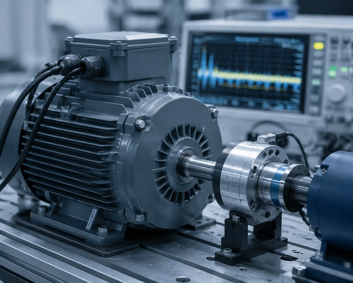
Asynchronous motor testing (three-phase induction motor testing) is the laboratory and on-site procedure that verifies a motor's efficiency class (IE code), insulation condition, starting performance, vibration severity, and squirrel-cage rotor integrity against IEC 60034-2-1, IEEE 112, GB/T 1032, IEC 60034-14 / GB/T 10068, and ISO 20816-3. It is not a single test but a sequence — insulation, no-load, locked-rotor, load, temperature-rise, and current-signature — that together decide whether a motor can be commissioned, repaired, or scrapped.
What Standards Govern Asynchronous Motor Testing?
Motor testing standards split into four families. The SERP sources rarely state which family governs which question, and the confusion between them is the main source of meaningless "it passed" claims.
- Loss-and-efficiency methods — IEC 60034-2-1 (Standard methods for determining losses and efficiency from tests), IEEE 112 (Standard Test Procedure for Polyphase Induction Motors and Generators, 2017), and GB/T 1032-2023 (三相异步电动机试验方法, implemented 2024-04-01). These define how to run the no-load test, the load test, and the stray-load-loss regression. GB/T 1032-2023 is "not equivalent" (NEQ) to IEC 60034-2-1 — it adopts the same principles but carries China-specific modifications for converter-fed motors.
- Efficiency classes — IEC 60034-30-1 defines the IE1 / IE2 / IE3 / IE4 / IE5 code for single-speed three-phase induction motors from 0.12 kW to 1000 kW, 2/4/6/8 poles, 50/60 Hz. The Chinese counterpart is GB 18613 (能效限定值及能效等级). Since 1 July 2021, motors from 0.75 kW to 1000 kW must meet a minimum of IE3 in many jurisdictions.
- Vibration severity — IEC 60034-14 / GB/T 10068-2020 (factory acceptance, no-load, uncoupled) and ISO 20816-3 (in-situ, on the bearing housing). These are different scopes: the first grades a new motor at the factory, the second grades an installed machine in service.
- Dielectric and insulation — IEC 60034-1 (rating, insulation, dielectric withstand) and GB/T 14711 set the withstand voltage, insulation resistance, and temperature-rise limits.
The fact the SERP sources obscure: the 4.5 mm/s vibration number that every maintenance guide quotes is the Zone B/C boundary of ISO 20816-3 (in-situ, installed machine), not a factory acceptance limit. The factory limit on a new motor — IEC 60034-14 / GB/T 10068, by shaft height and mounting — is tighter. A motor that passes the factory test can still sit in ISO 20816-3 Zone C in service if its foundation, alignment, or load coupling are wrong.
How Is Motor Efficiency Measured — and What Is the B Method?
Efficiency is the central deliverable of an acceptance test, and it is governed by the loss-separation methods. IEEE 112 Method B and IEC 60034-2-1 Method 2-1-1B and GB/T 1032 B法 are the same in principle: measure input and output power directly with a torque transducer, then determine the stray load losses by residual regression rather than assuming a fixed percentage.
The procedure:
- No-load test — run the motor uncoupled at rated voltage and frequency, then reduce the voltage in steps from ~125 % of rated down toward zero. Plot input power minus stator copper loss against voltage squared and extrapolate to zero voltage to separate the mechanical loss (friction + windage) from the iron (core) loss. These two are the "constant losses" — they do not depend on load.
- Load test — run the motor coupled to a dynamometer at six load points from ~25 % to ~150 % of rated load. At each point measure input power, output torque and speed, winding temperature, and current.
- Stray-load-loss regression — subtract the no-load constant losses, the stator I²R loss, and the rotor slip loss from the input-output difference at each load point. The remainder is the residual stray load loss; regress it against torque squared and reject the correlation if r² < 0.9 (a low correlation means the data is not self-consistent and the test must be repeated).
- Temperature correction — all copper losses are corrected to the reference winding temperature specified by the standard (the operating temperature reached at rated load), because winding resistance rises ~0.4 %/°C with copper temperature.
The IEEE 112-B and IEC 60034-2-1 methods give slightly different efficiency numbers on the same motor — a comparison on six motors (5.5–150 kW) showed the gap comes mainly from differences in stray-load-loss handling and temperature correction. For a defensible efficiency report the standard and the method letter must be cited explicitly; "efficiency = 93.2 %" without a method is unverifiable.
What Does the No-Load Current Reveal?
The no-load test is the cheapest diagnostic in the sequence, and the SERP sources quote its limit (no-load current 30–50 % of rated current for a standard motor) without explaining what a deviation means.
- No-load current well above 50 % — the air gap may be oversized (manufacturing defect or worn bearings), or the magnetic circuit is saturated (overvoltage, wrong connection such as delta-for-star).
- No-load current well below 30 % — wrong reconnection after a rewind (star-for-delta raises impedance and reduces current), or a high-resistance joint in one phase.
- Three-phase no-load current imbalance > 10 % — the rotor may have a cracked bar or end-ring fault, or the stator has a turn-to-turn fault that the resistance measurement missed.
- No-load input power higher than the catalog iron + mechanical loss — the bearings, the fan, or the seals are dragging, or the rotor is rubbing the stator.
The no-load current alone cannot diagnose any of these — but it tells the test engineer which downstream test to run next.
How Is Winding Insulation Tested — and Why Is a Megohm Reading Not Enough?
Insulation testing is the safety gate before any energized test, and it is the most commonly misread parameter in the SERP. The widely-quoted thresholds — ≥ 5 MΩ for a new motor, ≥ 0.5 MΩ for a long-stored motor at 500 V megohmmeter, and ≥ 1 MΩ/kV for the rated voltage of a high-voltage machine — are minimums to permit energizing, not statements that the insulation is healthy.
The full dielectric assessment is a layered sequence:
- Insulation resistance (IR) at the rated test voltage (500 V for ≤ 500 V windings; 1000 V per 1 kV of rating for higher voltages) — verifies no gross ground fault.
- Polarization index (PI) = IR at 10 minutes ÷ IR at 1 minute, at constant voltage. PI ≥ 2.0 indicates good insulation; PI < 1.0 indicates moisture or contamination. PI measures the dielectric absorption that a 60-second reading hides.
- Dielectric absorption ratio (DAR) = IR at 60 s ÷ IR at 30 s, a faster variant of PI.
- DC withstand (high-potential) test with leakage-current measurement — applies a DC voltage (typically a multiple of the RMS rated voltage) for one minute and monitors the leakage current; a rising or unstable current indicates weak insulation.
- AC withstand test — applies a power-frequency overvoltage (typically (2 × rated voltage + 1000 V) for 1 minute per IEC 60034-1) to verify the insulation system under realistic AC stress. This is a go/no-go test; the DC leakage test is the diagnostic one.
- Surge (impulse) test — the only test that reliably catches turn-to-turn faults. A capacitor is discharged into one phase and the damped RLC oscillation is compared against the other phases. A turn short changes the inductance and shifts the oscillation frequency; resistance can read normal while the surge test shows the fault. This is why the SERP note — "a multimeter is not enough" — is correct: a resistance measurement cannot see a turn-to-turn fault because the shorted turns are still electrically continuous.
How Is the Squirrel-Cage Rotor Diagnosed Without Dismantling?
The squirrel-cage rotor is the hardest part of an asynchronous motor to test directly, because its bars and end-rings carry no external connection. The SERP sources mention MCSA but do not give the mechanism.
Motor Current Signature Analysis (MCSA) detects rotor bar and end-ring faults from the supply current of a running motor. The principle: a broken bar or cracked end-ring breaks the magnetic symmetry of the rotor, which modulates the stator current at frequencies offset from the supply fundamental by ±2s·f (where s is the slip and f the supply frequency). For a 50 Hz motor at ~3 % slip, these pole-pass sidebands sit at ±3 Hz around the 50 Hz line — easily resolved by an FFT of the stator current. The sideband amplitude relative to the fundamental is the damage index: sidebands > -36 dB of the fundamental suggest broken bars; > -45 dB are usually acceptable.
MCSA's strength is that it runs on the operating motor without disassembly — critical for high-power motors and continuous-process drives. Its weakness is that load oscillations (a belt drive, a reciprocating pump, a gearbox) also produce sidebands near ±2s·f, which is why MCSA results must be read together with the load characteristic.
For a stator-side cross-check, the single-phase rotation test (apply reduced single-phase voltage, slowly rotate the shaft, observe stator current versus rotor angle) shows a current ripple whose depth scales with rotor asymmetry — a workshop method used when MCSA is ambiguous.
How Are Vibration Limits Set — Factory vs In-Service?
The vibration question "is 4.5 mm/s acceptable?" has no single answer; it depends on which standard and which condition. The two regimes are:
- Factory acceptance (new motor, no-load, uncoupled) — IEC 60034-14:2018 / GB/T 10068-2020 sets vibration velocity limits by shaft height and mounting (rigid vs flexible), measured at the bearing housing with the motor on its test bed. A new machine is held to a tighter limit than an installed one.
- In-service evaluation (installed, coupled, loaded) — ISO 20816-3:2022 (which supersedes ISO 10816-3) defines the four-zone severity scale on the bearing housing: Zone A (new machine, good), Zone B (long-term operation acceptable), Zone C (2.8–4.5 mm/s rms, marginal — plan repair), Zone D (> 4.5 mm/s rms, unacceptable — shut down).
A motor that reads 4.0 mm/s in service is in ISO 20816-3 Zone C — it can run but should be scheduled. The same 4.0 mm/s at the factory no-load test would likely fail the IEC 60034-14 limit. Quoting a single "vibration < 4.5 mm/s" pass line, as most SERP sources do, conflates the two regimes and gives a false pass.
Vibration frequency tells the fault: a peak at 1× running speed points to unbalance; 2× running speed to misalignment; pole-pass sidebands (running speed × number of pole pairs) to a rotor bar fault; non-integer harmonics to looseness or bearing defect — the same diagnostic logic as bearing vibration analysis, because the motor's rolling bearings are usually its first failure mode.
What Is the Locked-Rotor Test and the Temperature-Rise Test?
Two tests the SERP sources barely cover are decisive for whether a motor can be specified for a given application.
Locked-rotor (blocked-rotor) test — Chapter 10 of GB/T 1032 / IEEE 112 §6. With the rotor mechanically blocked, reduced voltage at rated frequency is applied to reach rated current, and the voltage, current, power, and torque are measured. This gives the starting torque, starting current, and the rotor/stator equivalent-circuit parameters under starting conditions. The locked-rotor current of a standard Design B motor is typically 6–7× rated current; the locked-rotor torque is typically 1.5–2.5× rated torque. The test is short (seconds) because the windings heat rapidly; it is also the test that defines whether the motor can start a high-inertia load without stalling or tripping the protection.
Temperature-rise test — the motor is run at rated load until thermal equilibrium (1 h temperature rise < 1 °C), and the winding temperature is measured by resistance (the resistance-rise method, using the copper temperature coefficient) or by embedded RTDs/thermocouples. The result is compared to the insulation class limit — for the common Class F (155 °C) system the winding temperature rise must not exceed 105 K (resistance method) at 40 °C ambient with the rated service factor. A motor that exceeds its class limit on the temperature-rise test will, by the 10 °C halving rule of insulation life, lose roughly half its insulation life for every 10 °C of overtemperature.
For large vertical motors where no dynamometer or load coupling is available, GB/T 1032 and IEEE 112 permit the mixed-frequency (superposition / dual-frequency) equivalent-load method — two power supplies of slightly different frequency are superimposed to drive the rotor back and forth between motor and generator operation, producing the equivalent load loss without an external mechanical load. Studies on this method report a temperature rise overestimate of 2–6 K and an efficiency underestimate of 0.5–1 percentage point relative to the direct load test.
Frequently Asked Questions
What standard governs asynchronous motor efficiency testing?
IEC 60034-2-1 internationally, IEEE 112 Method B in North America, and GB/T 1032-2023 in China. All three share the same structure: a no-load test to separate iron and mechanical losses, a load test at six points, and a stray-load-loss regression. GB/T 1032-2023 is "not equivalent" (NEQ) to IEC 60034-2-1, so the method and standard must be cited on the report.
What is the IE efficiency class system?
IEC 60034-30-1 defines IE1 (Standard), IE2 (High), IE3 (Premium), IE4 (Super-Premium), and IE5 for single-speed three-phase induction motors from 0.12 kW to 1000 kW. Since 1 July 2021, motors from 0.75 kW to 1000 kW must meet a minimum of IE3 in most jurisdictions. The Chinese counterpart is GB 18613.
Why is an insulation resistance reading not a complete insulation test?
A megohm reading verifies no gross ground fault but cannot detect turn-to-turn faults, dielectric weakness, or moisture-driven absorption. The full sequence is insulation resistance → polarization index (PI ≥ 2.0) → DC withstand with leakage-current measurement → AC withstand → surge test. The surge test is the only one that reliably catches turn-to-turn shorts, because a shorted turn is still electrically continuous and reads normally on a resistance meter.
How is a broken rotor bar detected without disassembly?
By Motor Current Signature Analysis (MCSA): an FFT of the stator current of the running motor shows sidebands at ±2s·f around the supply fundamental (50 Hz or 60 Hz), where s is slip and f is supply frequency. The sideband amplitude relative to the fundamental is the damage index; sidebands above about -36 dB of the fundamental suggest broken bars. Load oscillations can produce similar sidebands, so the load characteristic must be considered.
Is 4.5 mm/s vibration acceptable for a motor?
It depends on the standard and the condition. Under ISO 20816-3 (in-service, on the bearing housing), 4.5 mm/s rms is the Zone C/D boundary — the motor should be shut down. Between 2.8 and 4.5 mm/s rms it is in Zone C (marginal, plan repair). At the factory no-load acceptance test, IEC 60034-14 / GB/T 10068 set tighter, shaft-height-dependent limits. Quoting 4.5 mm/s as a universal pass line conflates the two regimes.
Our Testing Capabilities
Beijing ZKGX Research (ISO/IEC 17025 testing laboratory) supports asynchronous motor qualification from the insulation, electrical, vibration, and material-verification side. Where the IEC / IEEE / GB standards define the test procedure, we provide the diagnostic measurements and the failure-mode analysis that turn a pass/fail number into an engineering decision:
- Insulation condition — insulation resistance, polarization index (PI), dielectric absorption ratio, DC high-potential with leakage-current measurement, AC withstand, and surge (impulse) testing for turn-to-turn fault detection, per IEC 60034-1 and GB/T 14711.
- Winding resistance symmetry — four-wire (Kelvin) measurement of phase-to-phase DC resistance to detect inter-turn, phase-to-phase, and reconnection faults.
- Vibration measurement and analysis — vibration severity to ISO 20816-3 (in-situ) and IEC 60034-14 / GB/T 10068 (factory acceptance), with frequency-domain analysis (1×, 2×, pole-pass) for fault localization.
- Current signature analysis (MCSA) — FFT-based detection of broken rotor bars and end-ring faults, with sideband amplitude indexing.
- Temperature-rise verification — winding temperature by resistance-rise method and by embedded RTD/thermocouple, against the insulation-class limit (Class B / F / H).
- Lubricant and bearing-material verification — grease and lubricating-oil analysis (consistency, dropping point, viscosity, copper-strip corrosiveness) and bearing-steel cleanliness/hardness when a bearing failure is the suspected root cause.
If you have an asynchronous motor to commission, a premature failure to diagnose, or a rewind/repair to validate, contact our testing team to scope the applicable standards (IEC 60034 / IEEE 112 / GB/T 1032 / GB/T 10068), the sample conditions, and the acceptance criteria.