Electric motor testing is the systematic evaluation of a motor's electrical, mechanical, and thermal characteristics to verify it meets design specifications, safety requirements, and efficiency targets — before, during, and after its service life.
Electric motor-driven systems consume approximately 46% of the world's produced electricity. When a motor underperforms, the impact extends far beyond the motor itself. The Total Cost of Ownership (COO) breaks down as:
COO = Purchase Price + Cost of Running + Cost of Not Running
The cost of operating the motor — energy consumption and routine maintenance — typically accounts for 70–95% of total expense over a service life that can span 20 years or more. A motor that is 2% less efficient than rated can waste thousands of dollars annually in energy costs, while an unexpected failure can halt an entire production line.
According to the Electric Power Research Institute (EPRI), nearly 48% of all motor failures are electrical in origin: 36% from winding problems and 12% from rotor issues. The remaining 52% are mechanical — bearing failures, misalignment, and imbalance. Rigorous testing addresses both categories, catching defects early when repair costs are 5–10x lower than post-failure replacement.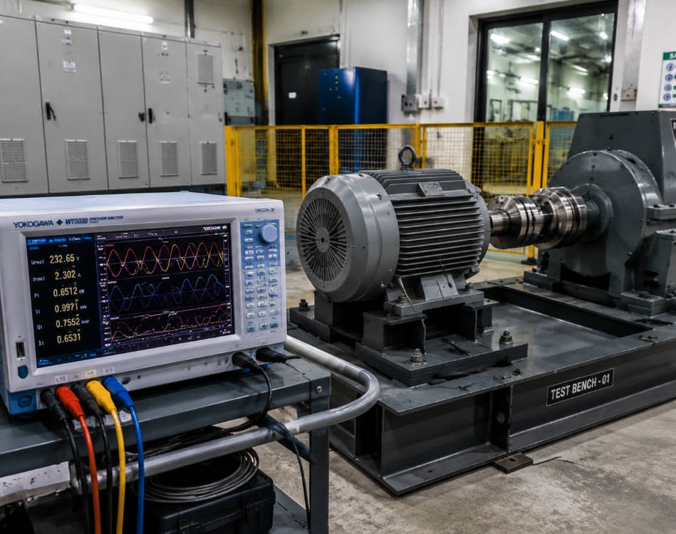
Key Electric Motor Testing Standards (IEC, IEEE, CSA)
Electric motor efficiency and testing methods are governed by a framework of international and regional standards. The three most important standard families are:
|
Standard |
Full Name |
Scope |
Key Methods |
|---|---|---|---|
|
IEC 60034-2-1 |
Rotating Electrical Machines — Losses and Efficiency |
International |
Calorimetric, input-output with loss segregation |
|
IEEE 112 |
Standard Test Procedure for Polyphase Induction Motors |
United States |
Methods A (brake), B (input-output with loss segregation), E/E1 (loss segregation) |
|
CSA C390 |
Energy Efficiency Test Methods for Three-Phase Induction Motors |
Canada |
Similar to IEEE 112 with tighter instrumentation requirements |
|
NVLAP 150 |
National Voluntary Laboratory Accreditation Program |
US accreditation |
Mirrors IEEE 112 2004; ±0.5% of full scale |
|
IEC 60034-30-1 |
Efficiency Classes (IE1–IE4) |
International |
Defines efficiency classes for motors 0.12–1000 kW |
|
IEEE 43 |
Insulation Resistance Testing |
International |
Temperature correction to 40°C; minimum resistance values |
|
IEEE 95 |
DC Step Voltage Testing |
International |
Graduated voltage increase; non-linear current indicates faults |
|
IEC 60034-14 |
Mechanical Vibration |
International |
Vibration severity grades and measurement methods |
Efficiency Classification (IE Codes)
|
IE Code |
Class |
Typical Efficiency Range (1 kW motor) |
Status |
|---|---|---|---|
|
IE1 |
Standard |
~75% |
Phased out in EU/US for most ratings |
|
IE2 |
High |
~82% |
Minimum in some regions |
|
IE3 |
Premium |
~85% |
Current minimum in EU (since 2021) |
|
IE4 |
Super-Premium |
~88% |
Increasingly required |
|
IE5 |
Ultra-Premium |
~91%+ |
Under development |
Electrical and Electromagnetic Testing
Electrical testing verifies that a motor's electrical parameters align with design specifications and that electromagnetic interactions are optimized for efficiency and minimal losses.
Key Electrical Parameters
-
Winding resistance and inductance: Evaluates copper losses and magnetic behavior. Measured with precision resistance meters (e.g., Hioki RM3545A) or LCR meters. Resistance imbalance between phases should not exceed 2–5%.
-
Insulation resistance: Ensures no short circuits develop between windings and motor frame. Measured with megohmmeter per IEEE 43, with temperature correction to 40°C.
-
Magnetic flux density: Determines the strength of the magnetic field within the motor, directly impacting torque and efficiency.
-
Electromagnetic field distribution: Identifies hotspots and irregularities in magnetic field lines, typically analyzed via finite element analysis (FEA) during design.
No-Load and Locked Rotor Tests
|
Test |
Condition |
What It Reveals |
|---|---|---|
|
No-load test |
Motor runs freely (no mechanical load) |
Core losses (iron), friction and windage losses, magnetizing current |
|
Locked rotor test |
Rotor held stationary |
Stator copper losses, starting current, starting torque, equivalent circuit parameters |
Partial Discharge (PD) Detection
Partial discharge testing detects minute electrical discharges within insulation systems — often precursors to major insulation failures. PD events are detected by observing current and voltage waveforms during withstand voltage testing. This is particularly valuable for medium-voltage (1–15 kV) motors where insulation degradation is a leading failure mode.
Mechanical and Vibration Testing
Approximately 50% of motor faults are mechanical in origin. Vibration analysis and structural testing are essential for identifying these issues before they escalate.
Vibration Analysis
Vibration analysis is performed using accelerometers mounted on bearing housings in three axes (horizontal, vertical, axial). Key fault signatures include:
|
Fault Type |
Frequency Signature |
Amplitude Characteristic |
|---|---|---|
|
Rotor imbalance |
1× running speed (1×RPM) |
Increases with speed |
|
Misalignment |
1×, 2×, or 3× RPM |
Axial vibration dominant |
|
Bearing defect (outer race) |
BPFO (ball pass frequency outer) |
Non-synchronous peaks |
|
Bearing defect (inner race) |
BPFI (ball pass frequency inner) |
Non-synchronous with sidebands |
|
Looseness |
0.5×, 1×, 1.5×, 2× RPM |
Harmonic series |
|
Eccentricity |
1× RPM + sidebands at line frequency |
Load-dependent |
Per IEC 60034-14, vibration severity is graded from A (new machines) through D (unacceptable), with RMS velocity limits ranging from 1.12 mm/s (Grade A, 56–70 mm shaft height) to 4.5 mm/s (Grade D).
Mechanical Parameters Analyzed via FEA
-
Bearing load and life expectancy: Force distribution on bearings to prevent premature wear (L10 life calculation)
-
Thermal expansion and stress: How temperature changes affect material properties and structural integrity
-
Fatigue analysis: Repeated load impact on motor components over time
-
Torque and rotational forces: Forces on shafts, couplings, and mounting structures
-
Mechanical resonance: Natural frequencies that could cause destructive vibrations under operational loads
thermal testing and Heat Management
Heat is the primary limiting factor in electric motor performance. Excessive temperatures damage windings, bearings, and insulation — reducing efficiency and accelerating aging.
Key Thermal Parameters
|
Parameter |
Why It Matters |
Typical Limit |
|---|---|---|
|
Winding temperature rise |
Insulation class defines maximum |
Class B: 80°C, Class F: 105°C, Class H: 125°C above ambient |
|
Heat dissipation efficiency |
Determines sustained output capacity |
Varies by cooling method (TEFC, ODP, liquid-cooled) |
|
Thermal gradients |
Uneven heating causes mechanical stress |
< 10°C gradient across frame |
|
Hot spot temperature |
Localized overheating precedes failure |
Must stay within insulation class rating |
|
Ambient temperature effect |
Motor derating above 40°C |
1% derating per 1°C above 40°C typical |
Thermal Testing Methods
-
Resistance method: Measures winding resistance change to calculate average temperature rise (R_hot/R_cold = (234.5 + T_hot)/(234.5 + T_cold) for copper)
-
Embedded detectors: Thermocouples or RTDs placed in windings during manufacture
-
Infrared thermography: Non-contact surface temperature mapping during operation
-
Thermal simulation (FEA/CFD): Computational fluid dynamics models heat transfer through conduction, convection, and radiation before physical prototyping
Insulation Classes and Temperature Ratings
|
Class |
Maximum Hot Spot Temperature |
Common Applications |
|---|---|---|
|
Class A |
105°C |
Small motors, low-duty applications |
|
Class B |
130°C |
General-purpose industrial motors |
|
Class F |
155°C |
Premium efficiency, heavy-duty motors |
|
Class H |
180°C |
High-temperature environments, crane motors |
|
Class C |
220°C |
Specialty applications |
Insulation Testing: Resistance, Polarization Index, and HiPot
Insulation testing is arguably the single most important category of motor testing, because insulation failure accounts for the largest share of electrical motor failures.
Insulation Resistance (IR) Testing
Measured with a megohmmeter (megger) applying high DC voltage (500V to 15 kV) to the windings. Per IEEE 43:
-
Minimum acceptable IR = rated voltage (kV) + 1 MΩ
-
Temperature must be corrected to 40°C (insulation resistance drops ~50% for every 10°C increase)
-
Three subcurrents measured: conductive leakage, capacitive charge leakage, and polarization absorption leakage
Polarization Index (PI) Testing
PI extends IR testing by measuring how resistance changes over time:
PI = R₁₀min / R₁min
|
PI Value |
Insulation Condition |
|---|---|
|
< 1.0 |
Dangerous — do not energize |
|
1.0–1.5 |
Questionable — investigate |
|
1.5–2.0 |
Fair — marginal for large motors |
|
2.0–4.0 |
Good |
|
> 4.0 |
Excellent |
A low PI value signals contamination, moisture ingress, or aging in the windings. The applied voltage should remain constant for the full 10-minute duration.
HiPot (High Potential) Testing
HiPot testing checks for adequate isolation between conductors and ground by applying voltages significantly above operating levels:
-
AC HiPot: Typically 2× rated voltage + 1000V for 1 minute
-
DC HiPot: Typically 1.7× (2E + 1000) for acceptance testing
-
Verifies insulation can withstand transient overvoltage events
DC Step Voltage Testing (IEEE 95)
Voltage is increased in predetermined steps every 60 seconds while current is plotted. A non-linear current response indicates insulation degradation — the test is more sensitive than megger testing alone for detecting localized defects.
Surge Testing
A transient voltage impulse is applied to windings to detect turn-to-turn insulation faults that megger and HiPot tests cannot find. The response waveform is compared between phases; any deviation indicates winding damage, voids, or layer shorts. Impulse winding testers (e.g., Hioki ST4030A) quantify response waveforms for higher precision than conventional techniques.
Performance and Efficiency Testing
IEEE 112 Test Methods
|
Method |
Description |
Power Range |
Accuracy |
|---|---|---|---|
|
Method A |
Brake/test dynamometer (input-output) |
≤ 1 kW |
Moderate |
|
Method B |
Input-output with loss segregation |
1–300 kW |
High (US standard) |
|
Method C |
Duplicate machines (back-to-back) |
Any |
High |
|
Method E |
Loss segregation (no load test + calculations) |
Any |
Good |
|
Method F |
Equivalent circuit calculation |
Any |
Moderate |
Loss Segregation (Method B)
Method B separates total losses into five categories for precise efficiency calculation:
|
Loss Category |
Source |
Typical % of Total Losses |
|---|---|---|
|
Stator copper loss (I²R) |
Current through stator windings |
25–40% |
|
Rotor copper loss (I²R) |
Current through rotor bars/end rings |
15–25% |
|
Core loss (iron) |
Hysteresis + eddy currents in laminations |
15–25% |
|
Friction and windage |
Bearings, seals, cooling fan |
5–15% |
|
Stray load loss |
Leakage flux, high-frequency losses |
5–15% |
Efficiency = Output Power / (Output Power + Total Losses) × 100%
Load Testing
Load testing measures motor response under various conditions:
-
Full load: Rated torque, speed, current, and temperature rise
-
Half load: Partial efficiency, power factor behavior
-
No load: Core losses, friction, magnetizing current
-
Overload (locked rotor): Starting torque, starting current, thermal withstand
Torque-Speed Characteristic
The torque-speed curve is the motor's fingerprint, revealing:
-
Starting (locked rotor) torque
-
Pull-up torque (minimum during acceleration)
-
Breakdown (maximum) torque
-
Full-load torque and speed
-
Synchronous speed and slip
Motor Testing Tools and Equipment
Essential Testing Instruments
|
Tool |
Function |
Price Range |
|---|---|---|
|
Digital Multimeter (DMM) |
Voltage, current, resistance, continuity |
$50–$500 |
|
Clamp-on Ammeter |
AC/DC current without disconnecting conductors |
$100–$800 |
|
Megohmmeter (Megger) |
Insulation resistance (500V–15kV DC) |
$300–$5,000 |
|
Power Quality Analyzer |
Three-phase power, harmonics, efficiency |
$1,000–$8,000+ |
|
Non-contact Thermometer |
Surface temperature measurement |
$30–$300 |
|
Vibration Analyzer |
FFT spectrum analysis, fault diagnosis |
$2,000–$20,000+ |
|
Surge/Impulse Tester |
Turn-to-turn insulation faults |
$3,000–$15,000 |
|
Precision Power Analyzer |
Motor + drive efficiency (e.g., Yokogawa WT series) |
$5,000–$30,000+ |
Current Sensors for Motor Testing
|
Sensor Type |
Frequency Range |
Accuracy |
Best Application |
|---|---|---|---|
|
DC shunt |
DC only |
±0.1% |
DC motors, low-frequency |
|
Hall Effect CT |
DC to ~100 kHz |
±0.5–1% |
VFD output, mixed frequencies |
|
Active-type CT |
DC to ~kHz |
±0.02–0.05% |
High-precision VFD measurement |
|
Standard CT |
30 Hz–400 Hz |
±0.2–0.5% |
AC line-powered motors |
Three-Phase Measurement Methods
-
Two-wattmeter method (3-wire): Uses two power elements per Blondel's theorem. Total power is accurate; individual phase power is not directly measurable without a floating neutral or delta measurement function.
-
Three-wattmeter method (4-wire): Direct measurement of each phase. Required when neutral is present.
-
Delta measurement function (Yokogawa): Derives true line-to-neutral voltage from instantaneous line-to-line measurements, even on unbalanced 3-wire systems — providing phase power without a physical neutral.
Online vs Offline Testing Strategies
A comprehensive motor maintenance program uses both online (dynamic) and offline (static) testing.
Online (Dynamic) Testing
Performed while the motor is operating under normal conditions. Captures:
-
Power quality: voltage level, voltage imbalance, harmonic distortion (THD)
-
Current levels and imbalances between phases
-
Load levels and torque signatures
-
Rotor bar condition (via current spectrum analysis)
-
Operating efficiency and power factor
Offline (Static) Testing
Performed when the motor is de-energized and disconnected. Captures:
-
Winding resistance and balance
-
Insulation resistance (IR), polarization index (PI)
-
DC step voltage response
-
Surge/impulse comparison between phases
-
Capacitance and dissipation factor
-
Winding inductance
Recommended Testing Frequency
|
Motor Criticality |
Online Testing |
Offline Testing |
|---|---|---|
|
Critical (production-stopping) |
Monthly |
Quarterly |
|
Important (redundant systems) |
Quarterly |
Semi-annually |
|
General purpose |
Annually |
Annually |
Emerging Trends: EV Motors, VFDs, and Digital Twins
Electric Vehicle Motor Testing
EV traction motors (permanent magnet synchronous or induction) require testing under highly dynamic conditions:
-
Torque ripple and cogging torque: Affects NVH (noise, vibration, harshness) in vehicles
-
Resolver and encoder calibration: Precise angle measurement for motor control algorithms
-
Regenerative braking efficiency: Energy recovery during deceleration
-
Wide speed range: 0 to 15,000+ RPM with constant power region
-
Thermal cycling: Repeated heating/cooling cycles degrade insulation faster than steady-state operation
Variable Frequency Drive (VFD) Testing
VFDs introduce PWM (pulse-width modulation) waveforms with high-frequency harmonics that complicate power measurement:
-
PWM output contains carrier frequencies of 2–20 kHz superimposed on the fundamental
-
Requires power analyzers with high bandwidth (>1 MHz sampling) and appropriate filtering
-
Motor efficiency must be measured separately from drive efficiency
-
Three-step process: (1) VFD input power, (2) VFD output/motor input power, (3) motor mechanical output
Digital Twins and Simulation-Driven Design
FEA and CFD simulation now serve as virtual test benches:
-
Electromagnetic FEA: Optimize slot/pole combinations, predict torque, back-EMF, and losses
-
Thermal CFD: Model heat dissipation paths, optimize cooling strategies
-
Structural FEA: Validate shaft, housing, and mounting designs under load
-
Combined multi-physics: Coupled electromagnetic-thermal-structural simulation for complete virtual validation
Simulation reduces physical prototype iterations by 40–60%, but FEA results must be validated against physical test data.
Summary
Electric motor testing spans electrical insulation assessment (megger, PI, HiPot, surge testing), mechanical vibration analysis, thermal characterization, and performance/efficiency measurement — governed by IEEE 112, IEC 60034, and CSA C390 standards. With motor-driven systems consuming 46% of global electricity, even a 1% efficiency improvement across the installed base translates to enormous energy savings. The key principle: test early, test often, and use both online and offline methods. A megger test takes 10 minutes and costs nothing compared to the $50,000+ expense of an unplanned motor failure on a critical production line.