Fuse testing is the set of type tests and routine tests that verify a fuse-link will interrupt a defined overcurrent within its rated voltage, breaking capacity, and time-current zone — and that it will not operate spuriously at currents it is designed to carry continuously. For low-voltage fuses the governing standard is IEC 60269-1 (Low-voltage fuses — Part 1: General requirements, published by IEC), adopted in China as GB/T 13539.1; for high-voltage current-limiting fuses it is IEC 60282-1 (IEC webstore). The test programme is not a single "does it blow" check — it is a sequenced verification of breaking capacity at three defined test currents (I₁ / I₂ / I₃), time-current characteristic within standardized "gates", I²t let-through, power dissipation, temperature rise, and mechanical strength, each tied to the fuse's utilization category.
What Is a Fuse's Utilization Category and Why Does It Decide the Test Programme?
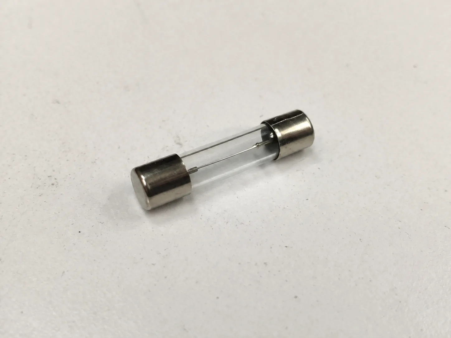
The two-letter utilization category (IEC 60269-1, Clause 5) is the single most important datum on a fuse nameplate because it tells the laboratory which characteristic curves and which breaking-range tests apply. The first letter encodes the breaking range; the second encodes the protected object:
- First letter — breaking range. g = full-range breaking (the fuse can interrupt all overcurrents from the smallest overload up to the rated short-circuit current); a = partial-range breaking (the fuse is designed to clear short-circuits only and must be paired with an overload device for low overcurrents). The full category table is given in the IEC 60269 utilization-category reference.
- Second letter — protected object. G = general-purpose cable/line protection (formerly gL); M = motor circuit; R = semiconductor (fast, low I²t); B = battery / mining; PV = photovoltaic string; N = North-American cable.
So a gG fuse is a full-range cable-protection fuse and is tested across the full breaking range; an aM fuse is a partial-range motor-circuit fuse and is not required to clear low overcurrents on its own — its type test reflects that. The practical consequence: a test report that does not state the utilization category is unverifiable, because the same rated current in gG vs aM vs gR corresponds to different time-current gates, different I²t limits, and different breaking test duties. This is the detail the SERP's "how to test a fuse" pages never surface.
What Standards Govern Fuse Type Testing?
Two standard families cover almost all industrial fuse testing:
| Scope | Standard | Notes |
|---|---|---|
| Low-voltage fuses — general requirements | IEC 60269-1 (GB/T 13539.1) | Type tests, breaking capacity, time-current gates, I²t, power dissipation, temp rise |
| LV — fuses for use by authorized persons | IEC 60269-2 (GB/T 13539.2) | Supplementary requirements (e.g. bolted, offset-blade) |
| LV — fuses for unskilled persons | IEC 60269-3 | Plug / semi-enclosed |
| LV — semiconductor protection | IEC 60269-4 (GB/T 13539.4) | aR / gR fast-acting, very low I²t |
| LV — auxiliary / miniature | IEC 60269-5 / -6 / -7 | PV (gPV), miniature fuse-links |
| High-voltage current-limiting fuses | IEC 60282-1 | Rated ≥ 1 kV; defines back-up, general-purpose, full-range categories |
| HV expulsion fuses | IEC 60282-2 | Different interrupting principle |
| North-American HV design tests | IEEE C37.41 | Equivalent duty definitions |
The North-American LV counterpart is the UL 248 series, which classifies by letter code (e.g. Class J, Class CC, Class T) rather than by the g/a + object scheme and which uses different breaking-test currents; a fuse certified to UL 248 cannot be assumed equivalent to one certified to IEC 60269, even at the same rated current and voltage. Fuse type testing therefore sits alongside our electric motor testing and surge / impulse immunity testing work — motor-circuit fuses (gM / aM) must be coordinated with the motor's starting current, and the let-through I²t directly governs the surge withstand of downstream electronics — and the cable-protection results feed the same coordination studies used in Fire-resistant cable tray testing and electrostatic discharge immunity testing.
How Is Breaking Capacity Tested — the I₁ / I₂ / I₃ Sequence?
The breaking-capacity test (IEC 60269-1, Clause 8.5; Tables 20–21 for AC, 22 for DC) is the headline type test. The fuse is mounted in a defined test circuit capable of delivering a prospective current (the current that would flow if the fuse were replaced by a link of negligible impedance) at a defined power factor and recovery voltage. Three test duties are run at three current levels:
- Test duty 1 — I₁, the rated breaking capacity. This is the maximum prospective current the fuse must interrupt (commonly 50 kA, 80 kA, 100 kA or up to 200 kA for industrial LV fuse-links, at the rated voltage). It verifies the fuse survives and clears the most severe fault. The circuit power factor for this duty is typically 0.2–0.3.
- Test duty 2 — I₂, an intermediate current chosen to produce the most severe arc energy condition. It is the duty that stresses the fuse element and filler most, and is the one most likely to expose a marginal design.
- Test duty 3 — I₃, a low overcurrent close to the conventional fusing current, relevant for full-range (g) fuses that must clear overloads, not just short circuits. For partial-range (a) fuses this duty is not required — by definition they need not clear low overcurrents alone.
Acceptance criteria (the same for all three duties): the fuse-link must interrupt the current; no sustained arcing, no flashover to ground or between terminals, no shedding of molten material, no rupture of the body; the arc must extinguish and the power-frequency recovery voltage must be held across the open fuse-link. Per GB/T 13539.1 the insulation resistance measured between fuse-link terminals after breaking must be ≥ 0.1 MΩ at a DC test voltage of twice the rated voltage (minimum 250 V). A breaking test in which the fuse clears but the body cracks, or in which the arc re-ignites, is a failure — "the element melted" is not by itself a pass.
How Is the Time-Current Characteristic Verified and What Are "Gates"?
The time-current characteristic (Clause 8.4 / Clause 9) is the fuse's identity curve: for each prospective RMS current it gives the virtual time to operation (pre-arcing time plus arcing time, with the arcing time bounded by the standard test circuit). The characteristic is not a single line — IEC 60269 defines it as a band delimited by standardized gates (conventional non-fusing current I_nf, conventional fusing current I_f, and a set of time-current gate points) within which every fuse of that utilization category and current rating must fall.
The gates enforce interchangeability: any manufacturer's 100 A gG fuse must clear the same overload in the same time band, so a gG fuse of a given size can replace another regardless of make. The verification test runs the fuse at several defined currents and checks that the operating time falls within the gate band — outside the band is a fail. For motor fuses the gM class carries a dual rating (e.g. 100M160: 100 A continuous, 160 A time-current), and the gate test must be reported against both numbers.
A consequence the SERP obscures: a fuse datasheet that quotes only "100 A" without the utilization category, the gate band, and the test standard is unverifiable — a 100 A gG, gM and gR fuse are three different protective devices with three different time-current bands.
What Is I²t (Let-Through Energy) and How Is It Tested?
I²t — the integral of the square of the let-through current over time, in A²·s — is the quantity that determines whether a downstream device or cable survives a fault. It is reported as two values: pre-arcing I²t (the energy up to the instant the element melts — the value that must be survived by anything in series that is not meant to operate) and arcing I²t (the additional energy during arc extinction); their sum is the total clearing I²t.
For semiconductor fuses (aR / gR per IEC 60269-4) the I²t value is the headline datasheet number, because the silicon junction's surge capability is itself specified as an I²t. For a gG or aM fuse the I²t is reported as maximum let-through values at defined prospective currents, and it is verified during the breaking-capacity test duties by integrating the captured current waveform. A low peak cut-off current and a low total I²t are how a current-limiting fuse protects a downstream contactor or cable from magnetic and thermal damage; both are measured, not calculated from a nameplate.
How Are Power Dissipation and Temperature Rise Tested?
A fuse is a series element that dissipates heat whenever it carries current, so its power dissipation at rated current (Clause 8.4, reported in watts) and its temperature rise at defined reference points are type-tested and reported. The test runs the fuse at rated current in a defined test arrangement (a defined conductor cross-section, a defined enclosure or open air, ambient (20 ± 5) °C) until thermal steady state; the power dissipation is measured and the temperature rise at the contact terminals must stay below the standard limit.
This matters for coordination: a fuse with high power dissipation raises the temperature of the surrounding switchgear, which de-rates every device near it. A common field failure mode — nuisance blowing or contact burn-back — is traceable to a fuse whose dissipation was higher than the enclosure was designed to dissipate. The power-dissipation value on a compliant datasheet is a measured type-test result, not a computed estimate.
How Are High-Voltage Fuses (IEC 60282-1) Tested Differently?
High-voltage current-limiting fuses (rated ≥ 1 kV) follow IEC 60282-1, and the most important difference from the LV world is the three fuse categories that the standard defines, because each category has a different breaking-test obligation:
- Back-up fuses — partial-range, short-circuit only. Must be paired with another device for overload. Tested only at high fault currents.
- General-purpose fuses — interrupt from the minimum melting current up to rated breaking, but only down to a current that the fuse can clear without sustained arcing.
- Full-range fuses — interrupt all currents from the smallest that melts the element up to the rated breaking capacity. The most demanding category, because the low-current clearing test is the hardest to pass without body damage.
The breaking test for HV fuses is organized into Way 1 and Way 2 test-duty sequences that verify the fuse at maximum breaking current, at currents producing maximum arc energy, and at low overcurrent (for general-purpose and full-range categories). The transient recovery voltage (TRV) the fuse must withstand is defined by the standard, and the test must show no external flashover and no body rupture under the recovery voltage.
Frequently Asked Questions
What standard governs low-voltage fuse type testing?
IEC 60269-1 (Low-voltage fuses — General requirements), adopted in China as GB/T 13539.1. It defines the type tests — breaking capacity (I₁/I₂/I₃), time-current gates, I²t, power dissipation, temperature rise, mechanical strength — and the utilization-category coding (gG, aM, gR, gB, gPV…). Supplementary parts IEC 60269-2 to -7 add application-specific requirements.
What is the difference between a gG and an aM fuse — and why does it change the test?
The first letter is the breaking range: g = full-range (clears overloads and short circuits), a = partial-range (short-circuit only). A gG fuse is type-tested at low overcurrent (Test duty 3 / I₃); an aM fuse is not, because by definition it must be paired with an overload device. A test report that omits the category cannot be checked against the correct gate band.
What are the I₁, I₂, I₃ breaking test duties?
I₁ is the rated breaking capacity (the maximum prospective fault current, e.g. 100 kA). I₂ is an intermediate current chosen to maximize arc energy — the duty most likely to fail a marginal element design. I₃ is a low overcurrent near the conventional fusing current, required for full-range (g) fuses only. All three must clear with no body rupture, no flashover, no arc re-ignition, and post-breaking insulation resistance ≥ 0.1 MΩ.
What is I²t and why does it matter?
I²t is the let-through energy (A²·s), split into pre-arcing and total clearing values. It is the quantity that decides whether a downstream cable, contactor or semiconductor survives the fault. For semiconductor fuses (aR/gR, IEC 60269-4) it is the headline datasheet number because the silicon junction's surge capability is itself an I²t.
Why are power dissipation and temperature rise type-tested?
Because a fuse is a series heating element. Its power dissipation (watts at rated current) and terminal temperature rise are measured in a defined arrangement at (20 ± 5) °C and must stay below standard limits. High dissipation de-rates adjacent switchgear and is a common root cause of nuisance blowing and contact burn-back.
How are high-voltage fuses tested differently?
Under IEC 60282-1, HV current-limiting fuses are classified as back-up, general-purpose, or full-range, each with a different breaking-test obligation. Breaking tests run as Way 1 / Way 2 duty sequences verifying maximum breaking current, maximum arc energy, and (for full-range) low overcurrent clearing, with a standardized transient recovery voltage.
Our Testing Capabilities
Beijing ZKGX Research (ISO/IEC 17025 testing laboratory) provides fuse type and routine testing across the low-voltage and high-voltage current-limiting ranges:
- Breaking-capacity testing to IEC 60269-1 / GB/T 13539.1 — Test duties I₁, I₂, I₃ at prospective currents up to the rated breaking capacity (AC and DC, per Tables 20–22), with prospective-current measurement, recovery-voltage verification, and post-breaking insulation-resistance check (≥ 0.1 MΩ).
- Time-current characteristic verification — gate-band conformance for gG / gM / aM / gR / gB / gPV utilization categories, conventional non-fusing and fusing currents (I_nf / I_f).
- I²t (let-through energy) — pre-arcing and total clearing I²t derived from captured fault-current waveforms, cut-off current reporting; semiconductor fuse (aR/gR) qualification to IEC 60269-4 / GB/T 13539.4.
- Power dissipation and temperature rise (IEC 60269-1 Clause 8.4) at rated current in the defined test arrangement, terminal temperature-rise measurement.
- High-voltage fuse testing to IEC 60282-1 — back-up / general-purpose / full-range breaking duties (Way 1 / Way 2), TRV verification.
- Mechanical and insulation — fuse-base mechanical strength, dielectric withstand, degree of protection (IP).
If you have a fuse-link to type-test, a utilization category to qualify, or a breaking-capacity / I²t / time-current report to verify against IEC 60269 or IEC 60282-1, contact our testing team to scope the applicable test duties, the prospective-current circuit, and the acceptance criteria.