Table of Contents
- What is robotic arm testing?
- The nine test categories of a robotic arm type test
- Performance testing per ISO 9283 / GB/T 12642
- The ISO 9283 performance metrics and formulas
- Repeatability classes: what RP value corresponds to which robot
- Payload testing: rated, maximum, and limit load
- Endurance and lifetime testing: MTBF and joint cycles
- safety testing per ISO 10218-1 / GB 11291.1
- Vibration, shock, and temperature-rise testing
- EMC testing of the arm as a source and victim
- Ingress protection (IP) and environmental sealing
- Calibration and traceability
- FAQ
- Our robotic arm testing capabilities
What is robotic arm testing?
Robotic arm testing is the measurement and validation of an industrial robotic arm — the manipulator itself, with its controller and end-effector — against the performance, safety, endurance, payload, environmental, EMC, and sealing standards that govern its placement on the market as a finished product. It is distinct from industrial robot system testing (which adds the integrated cell, safeguards, and human-robot interaction governed by ISO 10218-2 and ISO/TS 15066): a robotic arm type test answers the question "is this arm, as a standalone product, accurate, safe, durable, and reliable enough to ship?" — before it is ever integrated into a cell.
A modern 6-axis industrial robotic arm is the convergence of high-precision mechanical linkages, harmonic-drive or cycloidal reducers, brushless AC servomotors, absolute encoders, a safety-rated controller, and a teach pendant. Every one of these subsystems can degrade in a way that degrades the arm's performance or safety. The robotic arm type test verifies that, at the moment of shipment, the arm meets its data-sheet specifications for accuracy, repeatability, payload, and lifetime, and that it complies with the electrical-safety, EMC, environmental, and sealing standards required for its target market (CE Machinery Directive in the EU, UL/ANSI in the US, GB 11291.1 + GB/T 12642 in China).
The most important standards governing a robotic arm type test are: ISO 9283:1998 (international) / GB/T 12642-2013 (Chinese equivalent, identical adoption) for performance; ISO 10218-1:2011 / GB 11291.1-2011 for robot safety; GB/T 12643 (vocabulary) and GB/T 12644 (characteristic representation) for data-sheet declarations; CISPR 11 / GB 4824 for EMC; IEC 60068-2 series for environmental; and IEC 60529 / GB/T 4208 for ingress protection.
The nine test categories of a robotic arm type test
A complete type test of a robotic arm covers nine categories, each of which has its own standard, instrumentation, and pass/fail criterion. The nine categories together constitute the data package that proves the arm is ready for market.
| # | Test category | Primary standard | What it verifies |
|---|---|---|---|
| 1 | Performance | ISO 9283 / GB/T 12642 | Accuracy, repeatability, path accuracy, drift, warm-up |
| 2 | Safety | ISO 10218-1 / GB 11291.1 | Protective stop, single-fault, electrical safety, essential performance |
| 3 | Payload | ISO 9283 cl. 7 / data sheet | Rated, maximum, and limit load handling |
| 4 | Endurance / lifetime | Manufacturer spec; MTBF validation | Joint cycles, MTBF demonstration |
| 5 | Vibration and shock | IEC 60068-2-6/-27 / GB/T 2423.10/.5 | Mechanical robustness in transport and operation |
| 6 | Temperature rise | GB/T 5226.1 / IEC 60204-1; joint manufacturer data | Joint motor and reducer steady-state temperature rise |
| 7 | EMC | CISPR 11 / GB 4824 + IEC 61000-4 series / GB/T 17799.2 | Emissions and immunity |
| 8 | Ingress protection | IEC 60529 / GB/T 4208 | Dust and water sealing per port |
| 9 | Calibration | ISO 9283 cl. 6 / GB/T 20868 | Measurement traceability to national standards |
A robotic arm that passes all nine categories earns a type-test report that supports CE marking, UL listing, ANSI/RIA conformity, GB 11291.1 type-test submission to NMPA/SAMR, and the manufacturer's own data-sheet claims. A failure in any one category blocks the submission.
Performance testing per ISO 9283 / GB/T 12642
The most-cited single test on a robotic arm data sheet is its positioning repeatability (RP), measured per ISO 9283 (the international standard) or its identical Chinese adoption GB/T 12642-2013. The standard defines the test geometry, the test procedure, and the statistics.
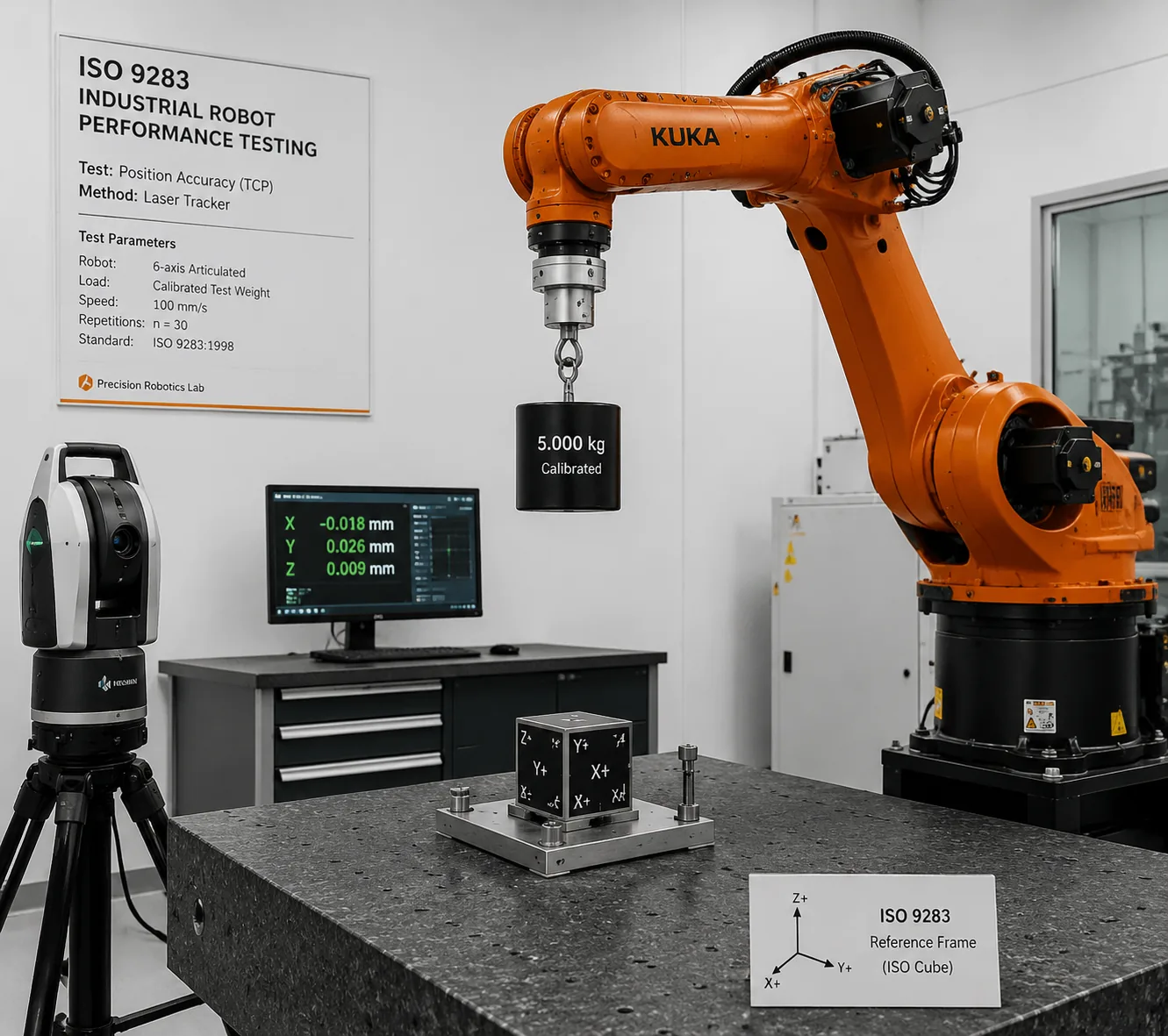
The ISO test cube. All measurements are taken inside the ISO test cube — the largest cube that fits inside the robot's reachable workspace, oriented with one diagonal vertical. Five standard test poses are defined within the cube: P1 at the centre, P2 through P5 at four corners of a single diagonal plane. The five-pose, 30-repetition protocol generates 150 measured points per metric, sufficient to compute the mean and standard deviation with adequate statistical power.
The measurement plane. For each pose, the attained position is sampled 30 times by returning to the commanded pose from a common approach direction. The laser tracker (or coordinate measuring machine, CMM) samples at ≥ 50 Hz, recording the x, y, z position of the tool centre point (TCP) at each arrival. The 30-point cloud per pose is then reduced to the accuracy and repeatability statistics defined by the standard.
Instrumentation. A laser tracker with a retroreflector mounted at the TCP is the reference instrument for modern robotic arm testing; portable CMMs (e.g. Faro Arm) and photogrammetric systems (e.g. C-Track) are acceptable alternatives with documented measurement uncertainty. The instrument's measurement uncertainty enters the uncertainty budget of the test report; for a laser tracker the typical uncertainty is ± 15 µm + 5 µm/m over a 10 m working volume, well below the RP values being measured.
The ISO 9283 performance metrics and formulas
ISO 9283 defines five primary performance metrics. Each has a specific mathematical definition; quoting the data-sheet number without citing the metric (e.g. "repeatability ± 0.05 mm" without specifying RP, at which payload, at which test pose, ISO cube) is a common source of cross-manufacturer mis-comparison.
| Metric | Symbol | Formula | Definition |
|---|---|---|---|
| Pose accuracy | AP | AP = √[(x̄ − x_c)² + (ȳ − y_c)² + (z̄ − z_c)²] | Deviation of the mean attained pose from the commanded pose, in 3-D |
| Pose repeatability | RP | RP = k̄ + 3·S_k, where k_i = distance of each attained pose from the centroid | Radius of the sphere centred on the mean attained pose that contains ~99.7 % of the 30 attained points |
| Path accuracy | AT | AT = max‖p̄(t) − p_c(t)‖ | Maximum deviation between the mean actual path and the commanded path along a trajectory |
| Pose stabilisation time | — | Time from commanded arrival to when the TCP settles inside a defined tolerance band | Settling-time characteristic; typically 0.1–0.5 s |
| Drift of pose / warm-up | — | Change in mean attained pose over time at a fixed commanded pose | Measured over a 10-minute to 4-hour warm-up period |
Of these, RP is the most-cited metric on a robotic arm data sheet, because in pick-and-place, welding, and assembly, returning to the same point every time is more important than hitting an absolute coordinate. The AP metric, by contrast, captures the systematic offset of the arm from its commanded position and is the metric that matters for absolute-coordinate tasks (drilling, machining, PCB probing) where the arm's kinematic model is relied upon.
A common misreading of the ISO 9283 test is to report only the best of the five test poses, or only at minimum payload, or only at room temperature. The standard requires reporting at the rated payload, at all five test poses, and at the rated ambient temperature; the reported RP value on the data sheet is conventionally the worst-case value across the five poses, which is the conservative figure the integrator can rely upon.
Repeatability classes: what RP value corresponds to which robot
The RP values quoted on modern robotic arm data sheets cluster into a few classes by arm category. These are the typical values against which a tested arm is compared:
| Arm category | Typical RP (ISO 9283) | Typical examples |
|---|---|---|
| High-precision 6-axis (machining, PCB, dispensing) | ±0.01 to ±0.03 mm | Stäubli TX2 series, Epson C4, Yamaha rotary selector |
| General industrial 6-axis (welding, handling) | ±0.04 to ±0.10 mm | FANUC M-20, KUKA KR CYBERTECH, ABB IRB 6700, Yaskawa GP-series |
| Collaborative 6-axis (cobot) | ±0.03 to ±0.10 mm | Universal Robots UR-series, FANUC CRX, Doosan M-series |
| SCARA (fast pick-and-place) | ±0.01 to ±0.04 mm | Epson SCARA, FANUC SR-series |
| Large-payload 6-axis (≥100 kg) | ±0.1 to ±0.3 mm | FANUC M-2000, ABB IRB 8700, KUKA KR 1000 |
| Delta / parallel (high-speed packaging) | ±0.05 to ±0.15 mm | ABB FlexPicker, FANUC M-1, Yaskawa MPP3S |
A 6NAPSE Group service page (Stäubli TX2-160) advertises repeatability ISO 9283: 0.05 mm, which places it in the general-industrial-6-axis class — consistent with its 40 kg payload and 1710 mm reach. An arm whose measured RP exceeds its data-sheet value fails the type test, and the failure must be investigated (joint encoder drift, reducer backlash, controller tuning, link thermal expansion) before the arm ships.
Payload testing: rated, maximum, and limit load
The payload test verifies that the arm handles its declared load across the workspace without degradation of the performance or safety functions. Three load levels are tested:
| Load level | Definition | What is verified |
|---|---|---|
| Rated load | The load at which all data-sheet performance values apply | RP at rated load, across the five ISO 9283 test poses; the reported RP value is measured at this load |
| Maximum load | The largest load the arm is rated to handle, with reduced performance | RP and AT may degrade at maximum load; the controller enforces a reduced-speed envelope |
| Limit load | The load at which the arm's mechanical structure or safety functions fail | Verified as a safety margin: the arm must not lose braking, holding, or protective-stop capability at limit load |
The test is performed with a calibrated mass attached to a standard tool flange, with the centre of mass offset by the data-sheet distance (typically 50–200 mm from the flange face). The arm executes a standard test cycle — pick at P1, place at P2, return — at 100 % rated speed for ≥ 1000 cycles, with the TCP position sampled continuously. A loss of RP of more than 1.5× the data-sheet value, or a failure of any safety function, fails the test.
Endurance and lifetime testing: MTBF and joint cycles
The endurance test is the longest-duration test on the type-test schedule and the one most often abbreviated or substituted by calculation in commercial labs. The objective is to demonstrate that the arm achieves its declared Mean Time Between Failures (MTBF) and that the joint reducers, motors, encoders, and cables survive the declared cycle count.
| Lifetime metric | Typical value | What is verified |
|---|---|---|
| MTBF | 50,000 to 100,000 operating hours (modern industrial arms); 30,000–50,000 h for cobots | Demonstration by accelerated cycling or by field-data accumulation |
| Joint reducer cycle count | 10⁷ to 10⁸ full-load cycles (harmonic drive / cycloidal reducer) | Continuous cycling at rated torque and speed; teardown and inspection at end of test |
| Cable flex cycle count | 10⁶ to 10⁷ flex cycles for the teach-pendant and end-effector cables | Flex test on a dedicated cable-flex rig, mimicking the arm's worst-case cable path |
| Brake engagement cycle count | 10⁶ engagement cycles per joint | Verified at full payload; brake holding torque measured before and after |
The full MTBF demonstration by direct testing at 50,000 operating hours is impractical for a type test, so manufacturers demonstrate MTBF by a combination of (a) accelerated life testing at elevated duty cycles (typically 150–200 % of rated speed and load, on a reduced-set of test poses), (b) teardown inspection of the joint reducers after 10⁷ cycles, and (c) field-MTBF accumulation from the installed base. The type-test report records the accelerated-cycle count, the teardown findings, and the calculated MTBF with its statistical confidence interval.
Safety testing per ISO 10218-1 / GB 11291.1
A robotic arm must satisfy ISO 10218-1:2011 (international) / GB 11291.1-2011 (Chinese mandatory equivalent) for the robot itself — distinct from ISO 10218-2 which governs the integrated system. The arm-level safety requirements include:
- Protective stop (category 0, 1, or 2) — verified at the maximum speed and maximum payload; the stopping time and stopping distance are recorded and published for use in cell-safety design.
- Single-fault condition — the arm must fail safe (move to a protective stop and not restart) under any single fault of the drive electronics, encoder, or safety controller; verified by fault injection.
- Emergency stop — must achieve Performance Level PLr e (SIL 3) per ISO 13849; verified by fault-injection testing of the e-stop chain.
- Speed and separation monitoring, power and force limiting (if the arm is sold as cobot-capable) — verified per ISO/TS 15066.
- Slow speed in manual (teach) mode — ≤ 250 mm/s TCP speed; verified by continuous sampling of the encoder at all joint configurations.
- Electrical safety — per IEC 60204-1 / GB/T 5226.1 (industrial machine electrical equipment); verified by dielectric strength, protective bonding, and residual-voltage tests.
- Mechanical safety — sharp-edge, pinch-point, and stability assessment per ISO 10218-1 Annex A.
A failure of any of these blocks the type test. The functional-safety file documenting the PL/SIL of each safety function is the most-queried single document in a CE Machinery Directive review and a NMPA submission.
Vibration, shock, and temperature-rise testing
| Test | Standard | Typical requirement | Purpose |
|---|---|---|---|
| Sinusoidal vibration | IEC 60068-2-6 / GB/T 2423.10 | 1 g, 10–500 Hz sweep, 3 axes, operating | Verifies joint encoder integrity, controller robustness |
| Shock | IEC 60068-2-27 / GB/T 2423.5 | 15 g, 11 ms half-sine, 3 axes, non-operating | Transport and handling shock survival |
| Damp heat steady state | IEC 60068-2-78 / GB/T 2423.3 | 40 °C / 93 % RH, 4–21 days | Controller and connector humidity robustness |
| Cold start | IEC 60068-2-1 | –5 °C to +5 °C, then verify motion | Cold-environment start-up |
| Temperature rise (joint) | GB/T 5226.1 + joint manufacturer data | ≤ 5 °C rise above ambient at the joint housing at steady state, rated duty | Verifies reducer and motor thermal design |
The temperature-rise test is particularly diagnostic: a joint that runs hot indicates either an under-sized motor, an over-tight reducer preload, or a degraded lubricant — any of which will shorten the arm's life. The 5 °C rise criterion is a conservative design target; the manufacturer's actual declared value, validated at the rated duty cycle and rated ambient, is recorded in the type-test report.
EMC testing of the arm as a source and victim
A robotic arm is a strong source of electromagnetic interference (the PWM-driven servomotors, the long motor cables, the controller switching) and a victim (the encoders, safety busses, and teach-pendant communication must remain immune to industrial EMI). EMC testing follows CISPR 11 / GB 4824 for emissions (Class A industrial or Class B residential) and IEC 61000-4 / GB/T 17799.2 for immunity.
| Test | Standard | Pass criterion |
|---|---|---|
| Conducted emissions (AC power port) | CISPR 11 / GB 4824 | Below Class A or B limit, 150 kHz–30 MHz |
| Radiated emissions (enclosure) | CISPR 11 / GB 4824 | Below Class A or B limit, 30 MHz–1 GHz |
| ESD immunity | IEC 61000-4-2 / GB/T 17626.2 | Performance criterion B, ± 4 kV contact / ± 8 kV air |
| Radiated RF immunity | IEC 61000-4-3 / GB/T 17626.3 | Performance criterion A, 10 V/m |
| EFT immunity | IEC 61000-4-4 / GB/T 17626.4 | Performance criterion B, ± 2 kV power port |
| Surge immunity | IEC 61000-4-5 / GB/T 17626.5 | Performance criterion B, ± 1 kV L-L / ± 2 kV L-G |
For a robotic arm's safety functions, the immunity criterion is effectively A — the protective stop, e-stop, and SSM/PFL functions must operate correctly during any industrial-environment EMI event, because the consequence of a missed safety function is uncontrolled motion into a worker.
Ingress protection (IP) and environmental sealing
| Test | Standard | Typical rating by arm class |
|---|---|---|
| Solid particle ingress | IEC 60529 / GB/T 4208 | IP4X (factory), IP5X (foundry), IP6X (food, cleanroom) |
| Water ingress | IEC 60529 / GB/T 4208 | IPX4 (splashing), IPX7 (1 m immersion), IPX9K (high-pressure jetting) |
A typical industrial 6-axis arm is rated IP54 (factory-class dust and splashing) on the arm body, with IP65 available as an option (Stäubli TX2-160 advertises IP65 on the whole arm). A foundry-line arm is IP67; a food-line arm is IP69K for high-pressure washdown. The IP rating is per-port — wrist, base, joint seals, controller enclosure — and the lowest-rated port determines the arm rating. A teardown of the seals after the IP test is recommended to verify that the seals survived without degradation.
Calibration and traceability
Every measurement in the type-test report must be traceable to national standards through an unbroken chain of calibrations. The laser tracker, the CMM, the force/torque sensor, the vibration shaker, the EMC test site, and the temperature data-acquisition system must each hold a valid ISO/IEC 17025 calibration certificate covering the parameter being measured. The laboratory itself must hold ISO/IEC 17025 accreditation for the specific test methods; the accreditation certificate's scope sheet is the proof that the lab is qualified to issue the type-test report. GB/T 20868-2007 (industrial robot performance test implementation guideline) is the Chinese reference for the laboratory's performance-test procedure.
FAQ
What is the difference between ISO 9283 and GB/T 12642?
GB/T 12642-2013 is the Chinese national standard that identically adopts ISO 9283:1998. A test report against one is acceptable against the other for most purposes; the underlying test procedure is identical. GB/T 12642 consolidated the older GB/T 12642-1990 (performance criteria) and GB/T 12645-1990 (test methods) into a single standard.
What is positioning repeatability (RP) and how is it measured?
RP is the radius of the sphere centred on the mean attained pose that contains approximately 99.7 % of the attained poses over 30 repetitions, per ISO 9283. It is computed as RP = k̄ + 3·S_k, where k is the distance of each attained pose from the centroid and S_k is its standard deviation. RP is the most-cited single performance metric on a robotic arm data sheet; typical values are ±0.02 to ±0.1 mm for industrial 6-axis arms.
What is the difference between ISO 10218-1 and ISO 10218-2?
ISO 10218-1 (GB 11291.1) governs the robot itself — the manipulator and its controller. ISO 10218-2 (GB 11291.2) governs the integrated system — the robot plus its end-effector, safeguards, cell, and the human-robot interaction. A robotic arm type test addresses ISO 10218-1; the integrator's cell validation addresses ISO 10218-2.
How is MTBF demonstrated for a robotic arm?
Full demonstration at 50,000 operating hours is impractical for a type test. MTBF is demonstrated by a combination of (a) accelerated life testing at 150–200 % of rated speed and load on a reduced set of poses, (b) teardown inspection of the joint reducers after 10⁷ full-load cycles, and (c) field-MTBF accumulation from the installed base. The reported MTBF carries a statistical confidence interval.
Does a robotic arm need CE marking and GB 11291.1?
Yes for both markets. CE marking under the EU Machinery Directive 2006/42/EC requires the ISO 10218-1 type-test report, the functional safety file, and the technical file. The Chinese market requires the GB 11291.1 type-test report (CMA/CNAS accredited), GB/T 12642 performance report, and GB/T 5226.1 electrical equipment compliance.
Our robotic arm testing capabilities
Beijing ZKGX Research (ISO/IEC 17025 accredited, CMA- and CNAS-accredited testing laboratory) provides complete robotic arm type testing across all nine categories, against the international and Chinese standard stack:
- ISO 9283 / GB/T 12642 performance — pose accuracy (AP), pose repeatability (RP), path accuracy (AT), pose stabilisation time, drift, warm-up, measured inside the ISO test cube with a laser tracker at the five standard test poses and 30 repetitions per metric.
- ISO 10218-1 / GB 11291.1 robot safety — protective stop, single-fault, e-stop (PLr e), slow-speed teach mode, electrical safety per IEC 60204-1 / GB/T 5226.1.
- Payload testing — rated, maximum, and limit load handling at 100 % rated speed, 1000-cycle minimum, with continuous TCP sampling.
- Endurance / lifetime — accelerated life cycling at 150–200 % rated duty, reducer teardown at 10⁷ cycles, cable-flex and brake-engagement cycle testing, MTBF demonstration with statistical confidence interval.
- Vibration and shock — IEC 60068-2-6 / GB/T 2423.10 sinusoidal vibration, IEC 60068-2-27 / GB/T 2423.5 shock, IEC 60068-2-78 / GB/T 2423.3 damp heat.
- Temperature rise — joint motor and reducer steady-state temperature rise at rated duty, recorded with thermocouples at the joint housing.
- EMC — CISPR 11 / GB 4824 emissions, IEC 61000-4 / GB/T 17799.2 immunity, in a 3 m semi-anechoic chamber.
- Ingress protection — IEC 60529 / GB/T 4208 IP rating, with teardown inspection of seals after test.
- Calibration and traceability — laser tracker, force/torque sensor, vibration shaker, EMC test site, and temperature DAQ each with ISO/IEC 17025 calibration; test procedure per GB/T 20868-2007.
Suitable arm categories include: 6-axis articulated arms; SCARA arms; Cartesian / gantry arms; parallel / Delta arms; collaborative arms; large-payload arms; and medical / surgical arms (which additionally require the IEC 60601-1 / GB 9706.1 medical-device stack described in our industrial robot testing article). Each project is delivered with a full data report (test protocol, instrument calibration certificates, raw measurement data, statistical analysis, single-fault simulation, classification conclusion) in English and/or Chinese, with CMA/CNAS stamping, ready for direct submission to EU notified bodies, UL, ANSI/RIA, or NMPA/SAMR. Contact Beijing ZKGX Research to scope the type-test battery applicable to your robotic arm and target market.