What is Composite material testing?
Composite material testing is the systematic evaluation of mechanical, thermal, and physical properties of engineered materials composed of two or more constituent materials with distinct characteristics. These tests measure critical performance parameters including strength, stiffness, fatigue resistance, and environmental durability to ensure composite materials meet design specifications and safety requirements.
Composite materials consist of a matrix phase (continuous) surrounding a reinforcement phase (embedded), creating materials with properties superior to individual components. Common composite types include fiber-reinforced polymers (FRP), metal matrix composites (MMC), and ceramic matrix composites (CMC), each requiring specialized testing protocols to characterize their unique anisotropic behavior.
Testing enables material characterization, quality control, design validation, failure analysis, and regulatory certification for applications spanning aerospace, automotive, marine, construction, sports equipment, and wind energy industries.
Why Composite Material Testing Matters
Composite material testing serves as the foundation for ensuring structural integrity, safety, and performance across critical applications where material failure can have catastrophic consequences.
Material Characterization: Testing determines fundamental mechanical properties including tensile strength, compressive strength, shear properties, and fatigue behavior essential for design calculations.
Quality Control: Systematic testing identifies manufacturing defects, material inconsistencies, and process variations that could compromise structural performance.
Design Validation: Testing verifies that composite structures can withstand intended loads, environmental conditions, and operational requirements throughout their service life.
Failure Analysis: Understanding failure modes and mechanisms enables design improvements and material optimization for enhanced reliability.
Regulatory Certification: Aerospace, automotive, and marine applications require documented testing data to meet stringent safety standards and regulatory requirements.
Material Development: Testing provides feedback for developing new composite formulations, manufacturing processes, and reinforcement architectures.
Fundamental Principles of Composite Behavior
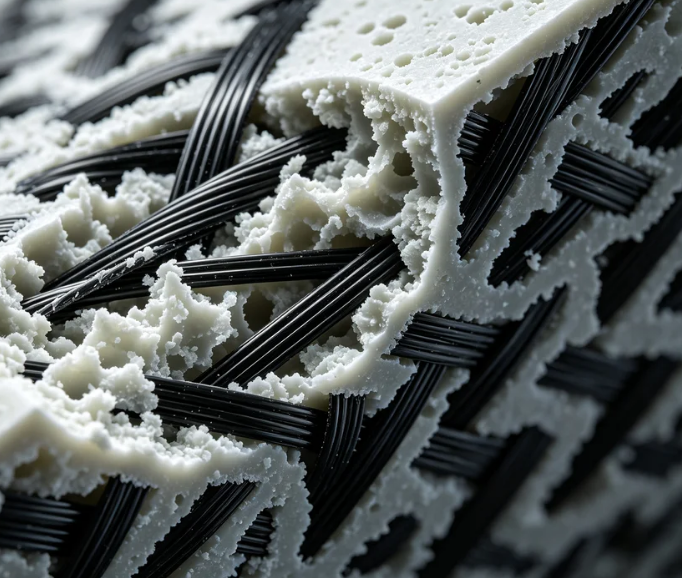
Anisotropic Properties
Composite materials exhibit anisotropic behavior, meaning mechanical properties vary significantly depending on the direction of applied load. This directional dependence distinguishes composites from isotropic metals and requires testing in multiple orientations.
Orthotropic Behavior: Many composites exhibit different properties in three mutually perpendicular directions—longitudinal (fiber direction), transverse, and through-thickness.
Testing Implications: Complete material characterization requires testing specimens with different fiber orientations (0°, 90°, ±45°) to capture directional property variations.
Design Considerations: Engineers must account for anisotropy when designing composite structures, optimizing fiber orientations for specific load paths and stress states.
Stress-Strain Relationships
Composite materials exhibit complex stress-strain behavior due to their heterogeneous nature and fiber-matrix interactions.
Linear Elasticity: Many composites show linear elastic behavior up to a certain stress level, followed by progressive damage accumulation before final failure.
Progressive Failure: Unlike metals, composites often fail through multiple damage mechanisms including matrix cracking, fiber breakage, delamination, and fiber-matrix debonding occurring sequentially or simultaneously.
Stress-Strain Curve Characteristics: Typical curves show initial linear region, possible non-linear region from matrix plasticity or debonding, and sudden stress drop at fiber failure.
Tensile Testing Methods and Standards
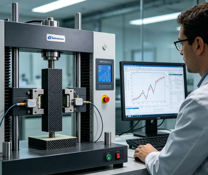
ASTM D3039 Standard Test Method
Tensile testing provides critical information about strength, stiffness, and behavior under uniaxial loading conditions. ASTM D3039 is the primary standard for polymer matrix composite materials.
Specimen Geometry:
-
Shape: Flat strips or rectangular cross-sections
-
Length: Typically 250 mm for unidirectional and fabric composites
-
Width: 25 mm for standard configurations
-
Thickness: 2-3 mm depending on material system
Specimen Preparation:
-
Cutting: Water-jet cutting or precision sawing with diamond-coated blades prevents delamination
-
Tab Bonding: End tabs prevent grip-induced failures for 0° fiber orientation specimens
-
Surface Preparation: Required for strain gauge application
Test Setup:
-
Universal testing machine with constant crosshead speed control
-
Hydraulic or mechanical grips with secure holding without specimen damage
-
Strain measurement via bonded gauges or extensometers
-
Data acquisition system for load, displacement, and strain recording
Longitudinal and Transverse Testing
Longitudinal Testing (0°):
-
Measures fiber-dominated properties
-
Results in higher strength and stiffness values
-
Failure occurs through fiber breakage
-
Critical for applications with primary loads aligned with fiber direction
Transverse Testing (90°):
-
Measures matrix-dominated properties
-
Results in lower strength and stiffness
-
Failure occurs through matrix cracking or fiber-matrix debonding
-
Important for understanding transverse load capacity
Data Analysis Parameters
Ultimate Tensile Strength (UTS): Maximum stress before failure Young's Modulus (E): Slope of stress-strain curve in linear region Poisson's Ratio (ν): Ratio of transverse to axial strain Strain at Failure (εf): Maximum strain before failure
Statistical analysis including mean values, standard deviation, and coefficient of variation accounts for inherent material variability.
Compression Testing Challenges and Solutions
ASTM D3410 Test Method
Compression testing is critical for applications where compressive loads dominate, such as aerospace structures. ASTM D3410 provides standardized methodology for in-plane compressive properties.
IITRI Fixture (Procedure B):
-
Wedge-shaped grip blocks apply compressive load through shear
-
Tapered wedge grips distribute load evenly across specimen width
-
Fixture design maintains alignment, reducing buckling risk
Combined Loading Compression (ASTM D6641):
-
Combines end loading and shear loading
-
Reduces end-crushing failures
-
Accommodates shorter specimens
Specimen Geometry Considerations
Length-to-Thickness Ratio: Unsupported length should be 4-6 times thickness to prevent global buckling
Width: Typically 6.4-12.7 mm for unidirectional composites, balancing representativeness and buckling prevention
Thickness: 1-6 mm depending on material and fixture requirements
End Tabs: Distribute gripping forces and prevent end-crushing, typically beveled at 30-60 degrees
Testing Challenges
Buckling Prevention: Thin laminates prone to buckling require careful fixture design and specimen geometry optimization
End Effects: Stress concentrations at loaded ends cause premature failure without proper tab design
Alignment: Misalignment introduces bending moments leading to invalid failures
Strain Measurement: Limited gauge length space requires small strain gauges or digital image correlation
Failure Mode Identification: Distinguishing valid compressive failures from buckling or end-crushing requires careful examination
Flexural and shear testing Methods
Flexural Testing (ASTM D7264)
Flexural testing determines material behavior under bending loads through three-point and four-point configurations.
Three-Point Bending:
-
Specimen supported at two points, loaded at midpoint
-
Simple setup with maximum stress at center
-
Flexural Strength: σf = 3PL / (2bh²)
-
Flexural Modulus: Ef = L³m / (4bh³)
Four-Point Bending:
-
Specimen supported at outer points, loaded at two inner points
-
Uniform bending moment between loading points
-
Reduced shear failure risk
-
Flexural Strength: σf = 3PL / (4bh²)
Specimen Considerations:
-
Length: 100-200 mm
-
Width: 13-25 mm
-
Span-to-thickness ratio: 16:1 (three-point), 32:1 (four-point)
In-Plane Shear Testing (ASTM D3518)
Test Principle: Tensile test on ±45° laminate induces in-plane shear state
Specimen Preparation: Balanced and symmetric ±45° laminate with dimensions similar to tensile specimens
Calculations:
-
Shear Stress: τ12 = P / (2A)
-
Shear Strain: γ12 = εx - εy
-
Shear Modulus: G12 = Δτ12 / Δγ12
Advantages: Uses standard tensile equipment, provides complete shear stress-strain curve
Interlaminar Shear Strength (ASTM D2344)
Short Beam Strength Test: Three-point bending on short beam induces interlaminar shear failure
Specimen Geometry:
-
Length = 6 × thickness
-
Width = 2 × thickness
-
Span length = 4 × thickness
Interlaminar Shear Strength: ILSS = 0.75 × P / (b × h)
Limitations: May not produce pure interlaminar shear failure; results affected by stress concentrations
Impact and Fatigue Testing
Impact Testing Methods
Charpy Impact Test:
-
Notched specimen supported as horizontal beam
-
Pendulum strikes specimen opposite notch
-
Measures energy absorbed during fracture
-
Specimen: 55 mm × 10 mm × 10 mm with V-notch or U-notch
Izod Impact Test:
-
Specimen clamped vertically
-
Pendulum strikes specimen on notched side
-
Good for thin sheet materials and anisotropic materials
-
Specimen: 64 mm × 12.7 mm × 3.2 mm
Composite Considerations:
-
Fiber orientation significantly affects results
-
Complex failure modes require multiple specimens with different orientations
-
Results affected by specimen size and notch geometry
Fatigue Testing (ASTM D3479)
Fatigue testing assesses performance under cyclic loading critical for long-term applications like wind turbine blades and aircraft structures.
Tension-Tension Fatigue:
-
Sinusoidal tensile load between minimum and maximum values
-
Stress ratio (R) typically 0.1 to 0.8
-
Frequency: 1-10 Hz
-
Generates S-N curves (stress vs. cycles to failure)
Compression-Compression Fatigue:
-
Sinusoidal compressive load with R > 1
-
Lower frequencies to avoid heating
-
Requires anti-buckling guides for thin specimens
Key Considerations:
-
Environmental effects significantly impact fatigue life
-
Damage accumulation involves matrix cracking, fiber breakage, and delamination
-
Stiffness degradation monitored throughout test
-
High data scatter requires statistical analysis
Environmental Effects on Properties
Moisture Absorption Testing
ASTM D5229 Method:
-
Specimens dried to constant weight
-
Immersed in water or exposed to controlled humidity
-
Periodically weighed until equilibrium
Moisture Content: M = [(W - W0) / W0] × 100%
Key Considerations:
-
Diffusion kinetics analysis
-
Edge effects simulation
-
Temperature acceleration effects
-
Fiber/matrix interface degradation
-
Property recovery after drying
Temperature Effects
Glass Transition Temperature (Tg):
-
Determined via Dynamic Mechanical Analysis (DMA) or Differential Scanning Calorimetry (DSC)
-
Significant property changes occur near Tg
Coefficient of Thermal Expansion (CTE):
-
Measured using dilatometry or strain gauges
-
Critical for predicting thermal stresses in multi-material systems
High-Temperature Testing:
-
Mechanical tests at elevated temperatures using environmental chambers
-
Important for aerospace and automotive applications
Thermal Cycling:
-
Simulates real-world temperature fluctuations
-
Monitors microcracking or delamination development
Combined Environmental Testing
Hygrothermal Aging: Combined moisture and temperature exposure monitoring property changes over time
Stressed Environmental Exposure: Constant load during environmental conditioning to assess creep behavior
Fatigue in Harsh Environments: Fatigue tests in environmental chambers to assess synergistic effects
UV Exposure: Weathering chambers simulate outdoor exposure for exterior applications
Non-Destructive Testing Methods
Ultrasonic Testing
Principles: High-frequency sound waves (1-50 MHz) transmitted through material; reflections analyzed for defects
Methods:
-
Pulse-Echo: Single transducer transmits and receives
-
Through-Transmission: Separate transmitter and receiver
-
Phased Array: Multiple elements for beam steering and focusing
Applications: Delamination detection, porosity assessment, thickness measurement, foreign object detection
Advantages: High sensitivity to internal defects, depth information capability
Limitations: Requires coupling medium, challenging for complex geometries
Thermography
Principles: Infrared cameras detect temperature differences indicating subsurface defects
Methods:
-
Passive Thermography: Observes natural temperature differences
-
Active Thermography: External heat source applied
-
Lock-in Thermography: Periodic heating with phase/amplitude analysis
Applications: Impact damage assessment, delamination detection, water ingress detection, bond quality evaluation
Advantages: Rapid large area inspection, non-contact method
Limitations: Limited depth penetration, surface condition sensitivity
X-ray Computed Tomography
Principles: X-rays attenuated differently by various features; multiple 2D images reconstructed into 3D volume
Methods:
-
Industrial CT: High-power sources for large components
-
Micro-CT: Very high resolution for small samples
-
In-situ CT: Combines scanning with mechanical testing
Applications: Fiber orientation analysis, void content measurement, impact damage assessment, quality control
Advantages: Detailed 3D information, non-destructive cross-sectioning
Limitations: Sample size limits, long acquisition times, radiation safety concerns
Data Analysis and Quality Control
Statistical Analysis Techniques
Basic Measures:
-
Mean: Central tendency of data
-
Standard Deviation: Spread around mean
-
Coefficient of Variation: Relative variability percentage
Advanced Techniques:
-
ANOVA: Determines significant differences between groups
-
Weibull Analysis: Probability of failure at different stress levels
-
Design of Experiments: Systematic factor-output relationship determination
Outlier Treatment: Statistical tests identify outliers; engineering judgment determines inclusion
Failure Mode Identification
Common Failure Modes:
-
Fiber Breakage: Clean break perpendicular to fiber direction
-
Matrix Cracking: Often first damage form
-
Delamination: Separation of adjacent plies
-
Fiber Pull-out: Indicates weak fiber-matrix interface
-
Buckling: Global or local instability
Identification Techniques: Visual inspection, optical microscopy, SEM, X-ray CT, acoustic emission
Property Prediction Models
Micromechanical Models:
-
Rule of Mixtures: Simple longitudinal property prediction
-
Halpin-Tsai Equations: Accurate transverse and shear properties
Laminate Theory:
-
Classical Laminate Theory (CLT): Predicts multi-directional laminate behavior
-
First Ply Failure Theories: Maximum Stress, Tsai-Wu criteria
Finite Element Analysis: Linear analysis for stress distributions; progressive failure analysis for damage simulation
Machine Learning: Neural networks and Gaussian process regression for property prediction
Advanced Composite Testing
Sandwich structure testing
Key Methods:
-
Flexural Testing (ASTM C393): Core shear properties
-
Flatwise Tensile (ASTM C297): Face sheet-core bond strength
-
Edgewise Compression (ASTM C364): Overall compressive strength
-
Core Shear (ASTM C273): Core material shear properties
-
Impact (ASTM D7766): Damage resistance evaluation
Considerations: Size effects, multiple failure modes, environmental effects on core properties
3D Woven Composite Testing
Modified Methods:
-
Tensile testing with larger specimens
-
Adapted compression testing for complex fiber architecture
-
Modified interlaminar shear tests
-
Fracture toughness (Mode I DCB, Mode II ENF)
-
Impact and compression after impact
Special Considerations: Fiber architecture characterization, scale effects, complex failure modes
Continuous Fiber 3D Printed Composites
Testing Methods:
-
Adapted tensile testing for print direction
-
Modified flexural testing for layer interfaces
-
Interlaminar shear for layer bonding quality
-
Compression testing for fiber alignment
-
Fatigue testing for long-term performance
Considerations: Print direction anisotropy, void content, fiber-matrix interface quality, residual stresses, surface finish effects
Industry-Specific Testing Requirements
Aerospace Industry
Critical Tests: Tensile, compression, fatigue, impact, environmental conditioning, non-destructive evaluation
Standards: ASTM, ISO, SAE aerospace specifications, CMH-17 handbook
Applications: Aircraft structures, spacecraft components, rotor blades requiring high strength-to-weight ratios
Automotive Industry
Critical Tests: Impact, fatigue, environmental exposure, crash simulation
Applications: Body panels, chassis components, structural reinforcements balancing weight reduction and crash safety
Marine Industry
Critical Tests: Environmental exposure, fatigue, impact, water absorption
Applications: Boat hulls, offshore platforms requiring corrosion resistance and long-term durability
Wind Energy Industry
Critical Tests: Fatigue, impact, environmental exposure, static strength
Applications: Turbine blades experiencing cyclic loading over 20+ year service life
Construction Industry
Critical Tests: Static strength, environmental exposure, fire resistance
Applications: Structural reinforcement, bridge components, seismic retrofit systems
Future Trends in Composite Testing
Digital Twin Integration
Combining physical testing with real-time simulation for improved prediction, optimization, and lifecycle management of composite structures.
Machine Learning Applications
Artificial intelligence for automated defect detection, property prediction, test plan optimization, and complex data interpretation.
High-Throughput Testing
Rapid testing methods to keep pace with accelerated material development cycles and comprehensive property databases.
Multi-Scale Testing
Integrating nano, micro, and macro-scale testing for comprehensive understanding of structure-property relationships.
In-Situ and Online Monitoring
Real-time property measurement during manufacturing and service through embedded sensors and advanced NDT techniques.
Automation and Robotics
Automated scanning systems for complex geometries and drone-based inspections for large structures.
Advanced Signal Processing
AI and deep learning for enhanced defect detection, classification, and improved resolution through sophisticated algorithms.