What Is Grooved Pipe Fittings Testing and Why Does It Matter? {#what-is-grooved-pipe-fittings-testing}
Grooved pipe fittings testing is the systematic process of verifying that mechanically joined pipe connections meet pressure integrity, fire resistance, material quality, and long-term reliability requirements before they enter service. Unlike welded or threaded joints, grooved connections depend on three interdependent components—ductile iron housing, elastomeric gasket, and fasteners—working as a system. Testing confirms this system performs under design pressure, temperature extremes, vibration, seismic loads, and fire exposure.
A single joint failure in a fire sprinkler main can disable an entire building's suppression system. In municipal water supply, a burst coupling floods infrastructure and shuts down service. The cost of failure—property damage, business interruption, legal liability—dwarfs the cost of testing. Hydrostatic testing alone, at 1.5× design pressure per ASME B31.3, catches the vast majority of defects before commissioning. Factory certification testing to UL 213 and FM 1920 adds a 4× rated pressure burst margin for life-safety systems.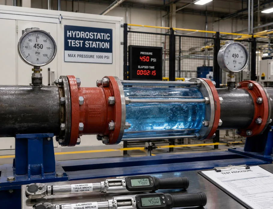
Key Testing Standards for Grooved Pipe Fittings {#key-testing-standards}
Grooved fittings fall under multiple overlapping standards depending on application, geography, and system type. The table below maps the primary standards to their scope and test requirements.
|
Standard |
Application |
Hydrostatic Test Pressure |
Burst Requirement |
Hold Time |
Key Focus |
|---|---|---|---|---|---|
|
ASME B31.3 |
Process piping |
1.5 × design pressure × (S_t / S_d) |
Proof test only |
≥10 min |
General pressure integrity |
|
UL 213 |
Fire protection fittings |
4 × rated pressure |
4 × rated pressure (min) |
60 sec min |
Life-safety, cyclic pressure |
|
FM 1920 |
Fire protection (property loss prevention) |
4 × rated pressure + bending/vibration |
4 × rated pressure |
Per spec |
Extreme real-world conditions |
|
AWWA C606 |
Water service grooved joints |
37.5 bar (544 PSI) |
≥75 bar (1,088 PSI) |
Per spec |
Groove dimensional compliance |
|
ASTM F1476 |
Mechanical couplings |
3 × rated pressure |
3 × rated pressure (min) |
Per spec |
Coupling performance |
|
ISO 6182 |
Fire sprinkler systems |
Aligns with UL 213 |
Per UL 213 |
Per spec |
International harmonization |
|
NFPA 13 |
Sprinkler system installation |
200 PSI or 50 PSI above working |
N/A (field test) |
2 hours |
Field acceptance testing |
Selecting the governing standard: For fire protection, UL 213 and FM 1920 are the toughest. For municipal water, AWWA C606 governs groove dimensions and hydrostatic proof. For industrial process piping, ASME B31.3 applies. Many manufacturers pursue dual or triple certification (UL + FM + CE) to satisfy global project requirements.
Hydrostatic Pressure Testing: The Foundation of Joint Integrity {#hydrostatic-pressure-testing}
Hydrostatic testing uses water—a non-compressible fluid—to pressurize grooved pipe assemblies and verify they hold without leakage, permanent deformation, or gasket extrusion. It is the single most important field test for any grooved piping system.
Test Pressure Calculation
The ASME B31.3 formula governs most industrial and water supply applications:
P_test = 1.5 × P_design × (S_t / S_d)
Where P_design is the system design pressure, S_t is allowable stress at test temperature, and S_d is allowable stress at design temperature. For ambient-temperature water systems where test and design temperatures are similar, the ratio S_t/S_d = 1.0, simplifying to P_test = 1.5 × P_design.
|
Design Pressure |
Test Pressure (1.5×) |
Typical Application |
|---|---|---|
|
150 PSI (10.3 bar) |
225 PSI (15.5 bar) |
Low-pressure distribution |
|
175 PSI (12.1 bar) |
263 PSI (18.1 bar) |
Standard sprinkler systems |
|
200 PSI (13.8 bar) |
300 PSI (20.7 bar) |
Industrial water loops |
|
250 PSI (17.2 bar) |
375 PSI (25.9 bar) |
High-rise fire protection |
|
300 PSI (20.7 bar) |
450 PSI (31.0 bar) |
Process water, high-demand systems |
End Load Force at Test Pressure
End load force is the axial thrust a grooved coupling must resist at test pressure. It is calculated as:
F_end = P × A
Where P is internal pressure and A is the pipe's internal cross-sectional area. For a 4-inch Schedule 40 pipe (OD 4.5″, wall 0.237″):
-
OD-based area: 15.90 in²
-
At 450 PSI test pressure: F_end = 450 × 15.90 = 7,155 lbs
-
At UL 213 burst test (1,200 PSI): F_end = 1,200 × 15.90 = 19,080 lbs
This force is transferred from the pipe groove through the coupling housing to the bolts. Undersized or improperly torqued fasteners fail under this load.
Step-by-Step Field Hydrostatic Test Procedure
-
System isolation: Remove or bypass all components rated below test pressure (relief valves, instruments, expansion joints). Install blind flanges at open ends.
-
Filling and venting: Fill from the lowest point. Open all high-point vents. Fill rate below 10 GPM to avoid hydraulic shock. Close vents only when water flows steadily from the highest point.
-
Initial pressurization: Raise to 50% of test pressure. Hold 5 minutes. Inspect all joints visually.
-
Incremental pressurization: Increase in 25% increments (50% → 75% → 100%) holding 2–3 minutes at each step.
-
Hold period: Maintain full test pressure for minimum 10 minutes (ASME B31.3) or 2 hours (NFPA 13 field test). Record pressure and temperature continuously.
-
Inspection during hold: Walk all joints checking for visible leakage, gasket extrusion, housing separation, sweating through castings.
-
Depressurization: Reduce at 25–50 PSI per minute. Never dump pressure rapidly.
-
Post-test bolt re-torquing: At zero pressure, verify all coupling bolts to manufacturer specification using a calibrated torque wrench.
Acceptance Criteria
A system passes if: no visible leakage, no pressure drop beyond thermal stabilization (typically <1–2%), no permanent deformation, no gasket extrusion.
A system fails if: any visible leakage (weeping, droplets, streaming), pressure drop >5% without temperature decrease, housing separation, bolt stretching, or gasket extrusion.
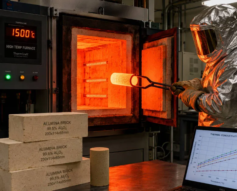
Fire Endurance Testing for Grooved Couplings {#fire-endurance-testing}
Fire endurance testing proves that grooved pipe joints maintain structural integrity and seal performance during direct flame exposure—a critical requirement for fire sprinkler systems that must deliver water while the building burns around them.
VdS Fire Exposure Test
VdS Schadenverhütung GmbH (Germany) conducts a fire exposure qualification test where the assembled joint is engulfed in concentrated fire at temperatures reaching 800°C (1,470°F) for 15 minutes. The coupling must maintain pressure and seal throughout. Similar tests include API-607 and UL-852 for high-hazard applications.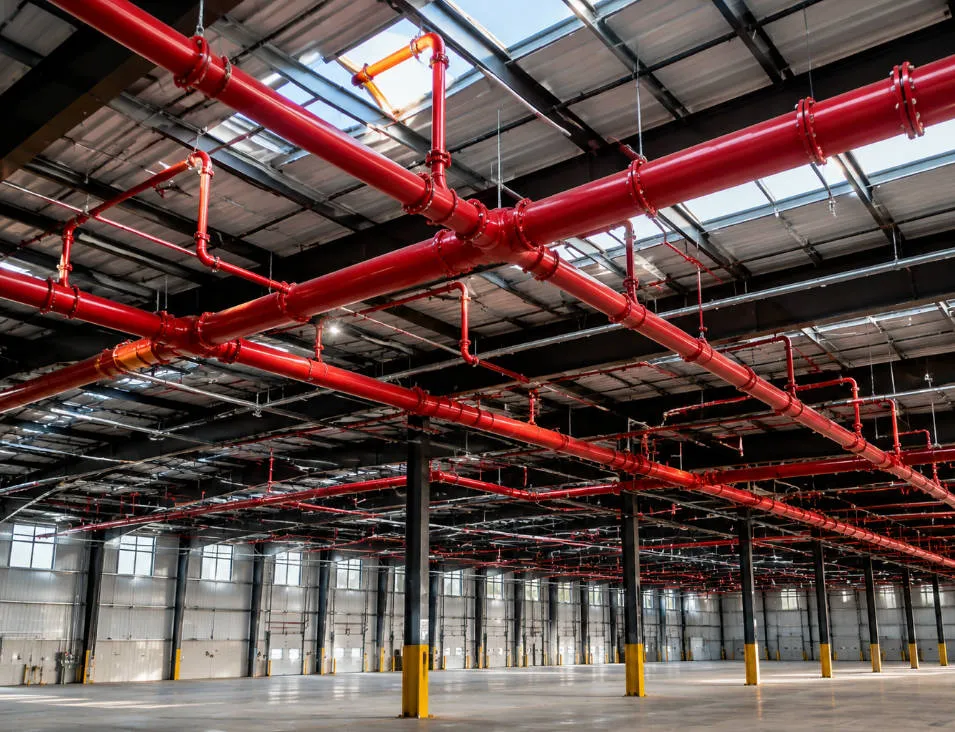
Ductile Iron Housing Performance
Grooved coupling housings cast from ductile iron per ASTM A-536 Grade 65-45-12 withstand direct fire exposure to temperatures exceeding 760°C (1,400°F) with no adverse effects to structural or metallurgical attributes. The housing acts as the first line of defense, shielding the internal gasket from direct flame.
Gasket Performance Under Fire Conditions
The gasket's compound formulation, manufacturing process, and material design all contribute to durability under direct fire exposure. The pressure-energized seal principle means higher internal pressure compresses the gasket harder against groove walls—even as external temperatures rise, internal water pressure maintains seal force.
FM Approval Testing: The Gold Standard for Fire Protection {#fm-approval-testing}
FM Approval (Factory Mutual) represents the most rigorous third-party certification for grooved pipe fittings in fire protection. Issued by FM Approvals—a division of commercial property insurer FM Global—the certification focuses on property loss prevention rather than minimum safety compliance.
What Makes FM Approval Different
|
Aspect |
FM Approval |
UL Listing |
|---|---|---|
|
Primary philosophy |
Property loss prevention |
Public safety (injury, fire, shock) |
|
Testing focus |
Extreme real-world conditions (fire, explosion, seismic) |
Established minimum safety standards |
|
Scope |
System-based; entire assembly evaluated |
Individual component against a standard |
|
Factory audits |
Frequent, often unannounced |
Regular, typically quarterly |
|
Standard |
FM 1920 for grooved couplings |
UL 213 for rubber-gasketed fittings |
FM Test Battery
FM Approval Standard 1920 subjects grooved fittings to:
-
Hydrostatic strength test: 4× rated working pressure without rupture. A 300 PSI coupling must survive 1,200 PSI.
-
Leakage test: Zero leakage at maximum rated working pressure for sustained duration.
-
Bending and assembly test: Coupling installed on pipe ends, subjected to significant bending moments and axial forces. Must maintain seal and structural integrity.
-
Vibration test: Pressurized assembly shaken at various frequencies and amplitudes simulating years of in-service vibration. Zero leakage allowed.
-
Vacuum test: Negative pressure to confirm gasket seals against external pressure.
-
Material verification: Metallurgical analysis confirms ductile iron chemical composition and microstructure.
-
Coating evaluation: Adhesion, thickness, corrosion resistance, and abrasion testing.
Ongoing Factory Surveillance
FM Approval is not a one-time event. Manufacturers face periodic, often unannounced factory audits verifying:
-
Raw material control (mill certificates, chemical composition)
-
Process control (casting, heat treatment calibration)
-
In-process and final inspection records
-
Finished product traceability (heat codes, lot numbers)
-
Drawing and document control (no unapproved design changes)
A manufacturer failing an audit can have approval suspended or withdrawn.
Verifying FM Approval Authenticity
The only definitive verification is the online FM Approval Guide at approvalguide.fmac.org. Physical "FM" marks cast into fittings are indicators but can be counterfeited. If a product bears the FM mark but is not listed in the Approval Guide, reject it.
Gasket and Seal Performance Testing {#gasket-seal-testing}
The elastomeric gasket is the seal core of every grooved joint. Testing gasket performance prevents the most common field failure mode: seal loss under pressure.
The Pressure-Energized Seal Principle
Grooved coupling gaskets are self-energizing—as internal pressure increases, the gasket lips expand against groove walls, creating a tighter seal. This means higher pressure improves sealing, up to the gasket material's limit. Testing validates this behavior across the full pressure range.
Four Primary Gasket Failure Modes
|
Failure Mode |
Cause |
Diagnostic |
Corrective Action |
|---|---|---|---|
|
Gasket extrusion |
Bolt torque below spec, groove out of tolerance, pressure exceeds rating |
Rubber pushed out of groove space |
Increase torque to spec, verify groove with GO/NO-GO gauge, reduce pressure |
|
Creep and compression set |
Aged gasket, elevated temperature, over-torqued bolts |
Permanent deformation, loss of bounce |
Replace gasket (EPDM: 10–15 year service), maintain temperature within rating |
|
Chemical degradation |
Incompatible fluid (EPDM exposed to hydrocarbons) |
Discoloration, cracking, softening |
Select correct material (EPDM for water, Nitrile for oil, Viton for chemicals) |
|
Uneven compression |
Non-uniform bolt torque |
Leak paths at low-compression zones |
Cross-tightening sequence (star pattern), calibrated torque wrench |
Gasket Material Selection for Testing
|
Material |
Temperature Range |
Best For |
Test Compatibility |
|---|---|---|---|
|
EPDM |
-40°C to 150°C |
Water, HVAC, fire protection |
Excellent with clean water |
|
Nitrile (NBR) |
-30°C to 120°C |
Oils, fuels, hydrocarbons |
Avoid water with additives |
|
Silicone |
-60°C to 230°C |
High-temperature, food processing |
Verify pressure rating |
|
Viton (FKM) |
-25°C to 200°C |
Aggressive chemicals |
Excellent for most chemicals |
Bolt Torque Testing and Joint Assembly Verification {#bolt-torque-testing}
Bolt torque is the single most critical field variable for grooved coupling performance. Even torque ensures uniform gasket compression; uneven torque creates leak paths.
Torque Specifications by Coupling Size
|
Coupling Size |
Bolt Size |
Torque Range (ft-lbs) |
Torque Range (N·m) |
Approx. Clamp Force (lbs/bolt) |
|---|---|---|---|---|
|
1½" – 2" |
5/8" |
45 – 60 |
61 – 81 |
4,500 – 6,000 |
|
2½" – 3" |
5/8" |
60 – 75 |
81 – 102 |
6,000 – 7,500 |
|
4" |
3/4" |
60 – 75 |
81 – 102 |
7,000 – 8,700 |
|
5" – 6" |
7/8" |
75 – 90 |
102 – 122 |
9,000 – 10,800 |
|
8" |
1" |
90 – 110 |
122 – 149 |
12,000 – 14,700 |
Cross-Tightening Sequence
Always tighten in a star (cross) pattern:
-
Hand-tighten all bolts
-
Apply 30% of target torque in cross sequence (Bolt 1 → 2 → 3 → 4)
-
Repeat at 60% of target
-
Apply final 100% torque in same sequence
-
Verify all bolts at target
Torque Tools
Use a calibrated torque wrench for final tightening. Impact tools (pneumatic/electric) are not acceptable for final torque because they provide inconsistent output, can over-torque and damage gaskets or bolts, and cannot verify final torque value.
Torque Loss and Re-Torquing Schedule
Approximately 10% of initial torque is lost within 24 hours due to material settling and gasket compression. Recommended schedule:
-
Initial torque at installation
-
Second torque after 24 hours (or after hydrostatic test)
-
Third torque after 30 days of service
-
Annual inspection and re-torque for critical systems
All re-torquing must be performed at zero system pressure.
Material and coating testing {#material-coating-testing}
Ductile Iron Material Verification
Grooved fitting housings are manufactured from ductile iron, typically ASTM A536 Grade 65-45-12. Testing confirms:
|
Property |
Typical Value |
Standard Requirement |
|---|---|---|
|
Tensile strength |
470+ MPa |
≥448 MPa |
|
Yield strength |
325+ MPa |
≥310 MPa |
|
Elongation |
14+% |
≥12% |
|
Hardness |
150–180 HB |
130–180 HB |
|
Impact resistance |
18+ J |
≥15 J |
Ductile iron is chosen for its combination of steel-like strength and cast iron corrosion resistance. The required ductility allows the housing to bend without fracturing under stress—a critical safety feature during seismic events or pressure surges.
Coating quality testing
|
Property |
Epoxy Coating |
Hot-Dip Galvanized |
|---|---|---|
|
Coating thickness |
65 µm (typical) |
70–85 µm |
|
Salt spray resistance |
1,000+ hours |
500+ hours |
|
Adhesion test |
ASTM D3359 Class 5A |
Metallurgical bond |
Coating testing includes adhesion (cross-hatch per ASTM D3359), thickness (magnetic gauge), and corrosion resistance (salt spray per ASTM B117). For fire protection fittings, red epoxy is standard; for water service, blue epoxy or hot-dip galvanized.
Roll Groove vs. Cut Groove: How Preparation Affects Test Results {#roll-vs-cut-groove}
The grooving method directly impacts hydrostatic test outcomes. Incorrect method selection for the pipe schedule causes preventable failures.
|
Parameter |
Roll Grooving |
Cut Grooving |
|---|---|---|
|
Method |
Hydraulic pressure displaces metal inward |
Machine cuts metal from pipe wall |
|
Best for |
Schedule 10 (light wall), Schedule 40 |
Schedule 40, Schedule 80, seamless pipe |
|
Pipe wall effect |
No wall thickness reduction; creates internal ridge |
Removes material; thinner wall, smooth interior |
|
Corrosion tolerance |
Higher (full wall maintained) |
Lower (reduced wall at groove) |
|
Critical failure risk |
Weld seam cracking if ERW pipe not annealed |
Burst hazard if applied to Schedule 10 |
Warning: Never cut groove a Schedule 10 pipe. The wall is already thin; removing material at the groove creates insufficient strength to withstand pressure, producing a burst hazard.
Pipe ovality is the most common cause of grooved system test failure. If the pipe is out-of-round beyond strict tolerances, groove depth varies around the circumference—too shallow and the housing key won't engage; too deep and the gasket won't seal. Specify pipes meeting ASTM A53 or ASTM A795 ovality tolerances.
Common Test Failures and Corrective Actions {#common-failures}
|
Failure Symptom |
Most Likely Cause |
Diagnostic Step |
Corrective Action |
|---|---|---|---|
|
Leakage at coupling during pressurization |
Insufficient bolt torque |
Check torque with calibrated wrench |
Increase torque to spec in cross sequence |
|
Leakage stops as pressure increases |
Gasket not seated; pressure energizing seal |
Verify pipe ends fully seated |
Disassemble, clean groove, re-seat, re-torque |
|
Sudden pressure drop, no visible leak |
Trapped air in system |
Check venting procedure |
Re-vent, re-fill, re-test |
|
Gasket extrusion visible |
Groove depth excessive or pressure exceeds rating |
Measure groove depth with GO/NO-GO gauge |
Replace with AWWA C606-compliant pipe |
|
Coupling housing separation |
End load exceeds bolt capacity |
Verify pipe size and pressure rating |
Upgrade to higher-rated coupling |
|
Intermittent weeping |
Non-uniform bolt torque |
Check torque on all bolts |
Re-torque with cross sequence |
|
Pressure holds then drops after 10+ min |
Temperature stabilization |
Monitor temperature throughout test |
Allow thermal equilibrium before re-test |
Systematic Troubleshooting Protocol
-
Safety first: Depressurize immediately. Never repair under pressure.
-
Document: Photograph failed joint. Record test pressure, temperature, conditions.
-
Isolate root cause: Remove coupling. Inspect gasket for extrusion or damage. Measure groove dimensions. Check bolt torque history.
-
Correct: Replace damaged components. Re-prepare pipe ends if groove is non-compliant.
-
Re-test: Repeat full hydrostatic test. Document all repairs and results.
Summary {#summary}
Grooved pipe fittings testing is not optional—it is the engineering proof that mechanical pipe joints will perform under pressure, fire, vibration, and time. Three numbers define the testing landscape: 1.5× design pressure (ASME B31.3 field hydrostatic test), 3× rated pressure (ASTM F1476 mechanical coupling proof), and 4× rated pressure (UL 213 / FM 1920 fire protection burst test). Bolt torque is the single most critical field variable—use a calibrated torque wrench, cross-tightening sequence, and never substitute impact tools for final torque. The gasket is the seal core; match material to service (EPDM for water, Nitrile for oil, Viton for chemicals) and inspect for extrusion, compression set, and chemical degradation after every test. A system that passes hydrostatic testing will perform reliably for decades; one that fails requires root-cause investigation, not re-pressure.
FAQ {#faq}
What is the standard hydrostatic test pressure for grooved pipe fittings? For ambient-temperature water supply per ASME B31.3, the test pressure is 1.5× design pressure. A 300 PSI system tests at 450 PSI. For fire protection certified to UL 213, factory burst testing requires 4× rated pressure (1,200 PSI for a 300 PSI fitting), though field testing follows NFPA 13 at 200 PSI or 50 PSI above working pressure.
How long should hydrostatic test pressure be held? ASME B31.3 requires a minimum of 10 minutes. NFPA 13 field tests typically run 2 hours. Complete water supply system tests commonly hold 1–2 hours for thermal stabilization and thorough joint inspection.
Can air replace water for hydrostatic testing of grooved fittings? No. ASME B31.3 permits pneumatic testing only where water contamination is unacceptable. Compressed air stores enormous energy and creates explosion hazards upon failure. Water is non-compressible, stores minimal energy, and provides safer, more reliable test results.
What is the most common hydrostatic test failure in grooved couplings? Insufficient or non-uniform bolt torque. When bolts are not torqued to manufacturer specification or tightened unevenly, the gasket experiences inadequate compression, creating leak paths. The second most common cause is improper pipe-end preparation—grooves not conforming to AWWA C606 dimensions.
Do grooved fittings require re-torquing after hydrostatic testing? Yes. Re-torquing must be performed at zero system pressure using the same cross-tightening sequence. Approximately 10% of initial torque is lost within 24 hours. Re-torque after the test, after 30 days of service, and annually for critical systems.
What gasket material is used for potable water hydrostatic testing? EPDM (ethylene propylene diene monomer) is the standard for potable water. It handles -40°C to 150°C, is compatible with water and wastewater, and resists compression set. For systems exposed to oils or hydrocarbons, use Nitrile (NBR) gaskets instead.
What is FM Approval and how does it differ from UL Listing? FM Approval originates from property insurer FM Global and focuses on preventing property loss under catastrophic conditions. UL Listing focuses on public safety. FM tests are often more extreme (4× burst, vibration, bending), and FM conducts unannounced factory audits. Both are highly respected; many products carry dual certification.
References {#references}
-
ASME B31.3-2022. Process Piping. American Society of Mechanical Engineers.
-
UL 213-2021. Standard for Rubber Gasketed Fittings for Fire-Protection Service. Underwriters Laboratories.
-
FM Approvals Standard 1920. Grooved Couplings and Fittings for Steel Pipe. FM Global.
-
AWWA C606-2022. Grooved and Shouldered Joints. American Water Works Association.
-
ASTM F1476-19. Standard Specification for Performance of Gasketed Mechanical Couplings. ASTM International.
-
ASTM A536-84(2019). Standard Specification for Ductile Iron Castings. ASTM International.
-
NFPA 13-2022. Standard for the Installation of Sprinkler Systems. National Fire Protection Association.
-
ISO 6182-1:2021. Fire Protection — Automatic Sprinkler Systems. International Organization for Standardization.
-
EN 10242:1994/A2:2003. Threaded Pipe Fittings in Malleable Cast Iron. European Committee for Standardization.
-
ASTM B117-19. Standard Practice for Operating Salt Spray (Fog) Apparatus. ASTM International.